Mobile unit information sharing system

a mobile unit and information sharing technology, applied in the direction of vehicle position indication, broadcast service distribution, instruments, etc., can solve the problems of inability to check the position information of other stations, inability to effectively utilize communication slots, and difficulty in information sharing not only between the headquarters and the mobile stations but also among the mobile stations

Inactive Publication Date: 2006-01-05
MITSUBISHI ELECTRIC CORP
View PDF7 Cites 45 Cited by
  • Summary
  • Abstract
  • Description
  • Claims
  • Application Information

AI Technical Summary

Benefits of technology

[0008] It is therefore an object of the present invention to provide a mobile unit information sharing system with which it is possible by wireless communications and without providing a communications control station to efficiently share not only voice data but also position information of multiple mobile stations and business information such as images shot in the course of business and instructions and the like, and with which movement tracking and management of multiple mobile units is possible by each station displaying on a map screen not only its own position but also the positions of other mobile units obtained through communications together with their paths traveled.
[0009] To achieve these and other objects, the present invention provides a mobile unit information sharing system in which a base station and multiple mobile stations carry out wireless communications and the base station and the mobile stations each have a wireless installation for executing wireless communications among the stations using a common wireless frequency, a time-sharing synchronous wireless modem device for receiving position information of the own station through a GPS antenna and transmitting this received own station position information to the other stations via the wireless installation and receiving position information of the other stations from the wireless installation, and a position information display device for receiving own station position information and other station position information from this time-sharing synchronous wireless modem device and recording it as shared data and displaying the position information on a map, wherein the time-sharing synchronous wireless modem device is made up of a GPS receiver part for receiving own station position information through the GPS antenna, a wireless modem part for modulating the own station position information received by this GPS receiver part to a data form used by the wireless installation and demodulating the other station position information received by the wireless installation from the data form used by the wireless installation, and a first computing part for transmitting the own station position information received from the GPS receiver part and the other station position information demodulated by the wireless modem part to the position information display device and transmitting the own station position information to the other stations via the wireless installation with transmission timing determined so that communication collisions do not occur, each station sharing position information by transmitting and receiving position information to and from the other stations.
[0010] With this invention, because, as described above, a base station and multiple mobile stations carry out wireless communications and the base station and the mobile stations each have a wireless installation for executing wireless communications among the stations using a common wireless frequency, a time-sharing synchronous wireless modem device for receiving position information of the own station through a GPS antenna and transmitting this received own station position information to the other stations via the wireless installation and receiving position information of the other stations from the wireless installation, and a position information display device for receiving own station position information and other station position information from this time-sharing synchronous wireless modem device and recording it as shared data and displaying the position information on a map, and the time-sharing synchronous wireless modem device is made up of a GPS receiver part for receiving own station position information through the GPS antenna, a wireless modem part for modulating the own station position information received by this GPS receiver part to a data form used by the wireless installation and demodulating the other station position information received by the wireless installation from the data form used by the wireless installation, and a first computing part for transmitting the own station position information received from the GPS receiver part and the other station position information demodulated by the wireless modem part to the position information display device and transmitting the own station position information to the other stations via the wireless installation with transmission timing determined so that communication collisions do not occur, each station sharing position information by transmitting and receiving position information to and from the other stations, the mobile stations can conduct time-sharing synchronous communications without the mediation of a communications control station, even when communications with the base station are cut off, without communication collisions between the mobile stations occurring, information can be shared among the multiple mobile stations by the communication of position information being carried out automatically, and by means of the position information display device not only the own station position but also the positions of the other stations which have conducted transmission and reception can be confirmed on a map.

Problems solved by technology

With a mobile unit communication system that transmits and receives voice signals using a common wireless frequency of related art such as that of JP-A-2001-43500 (Patent Document 1), although individual information on the mobile units can be managed at the central station, there has been the problem that on the mobile unit side it is not possible to check position information of other stations-on a display and information of the mobile units cannot be shared among the stations.
In information sharing systems using wireless communications of related art such as those of JP-A-2001-188837 and JP-A-2001-289642 (Patent Documents 2, 3), because as mentioned above an information sharing server manages the shared information and controls the communications, there has been the problem that when this server fails to function normally, information sharing not only between the headquarters and the mobile stations but also among the mobile stations becomes difficult.
And, when transmitting high-volume data such as images, even if there are empty time slots that no other station is using, there has been the problem that because data can only be transmitted within the transmission periods allocated to the stations, the communications slots cannot be utilized effectively, and information cannot be shared efficiently.

Method used


Image

  • Mobile unit information sharing system
  • Mobile unit information sharing system
  • Mobile unit information sharing system

Examples


first preferred embodiment

[0040] A first preferred embodiment of the invention will now be described on the basis of the drawings.

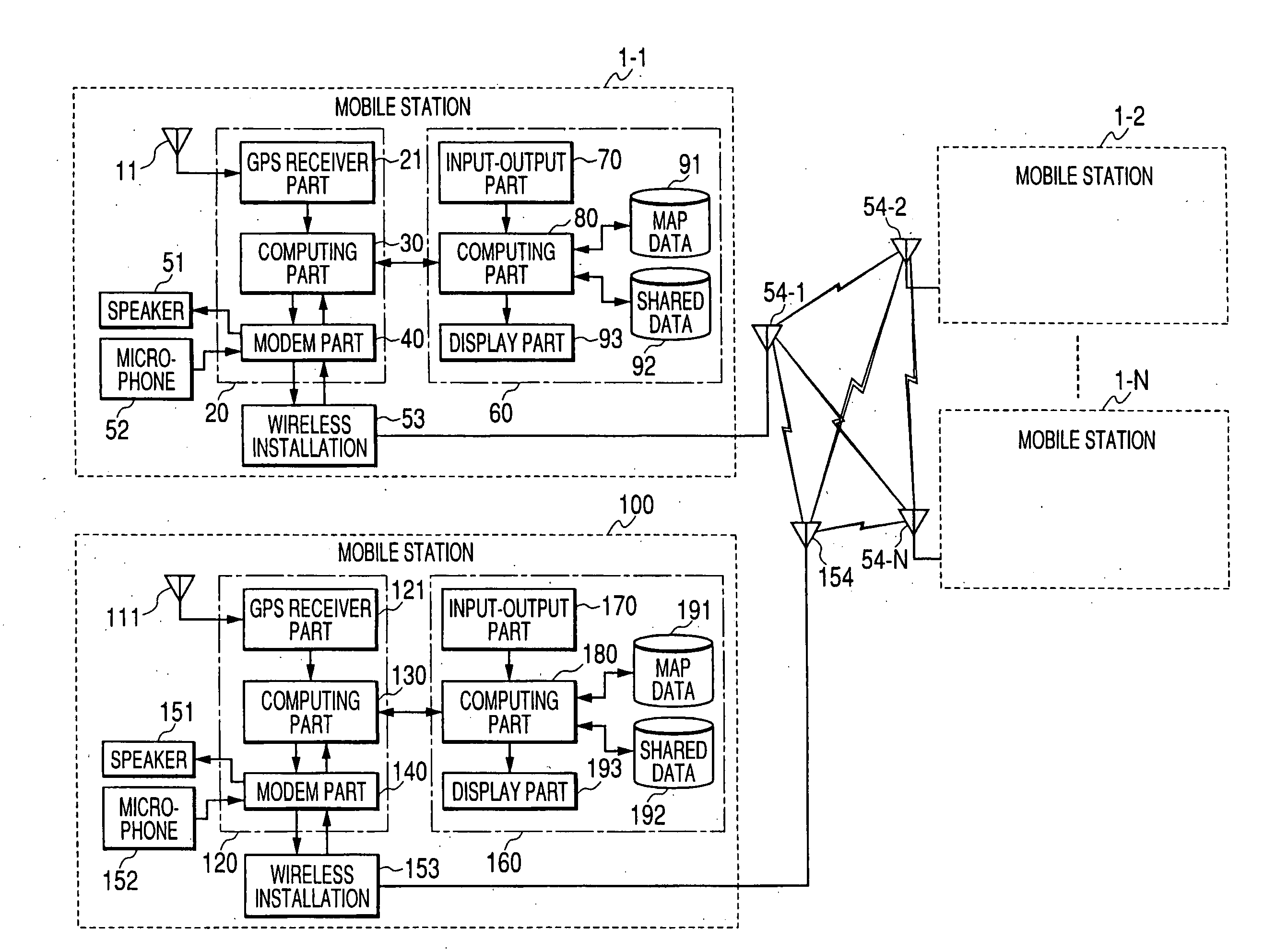
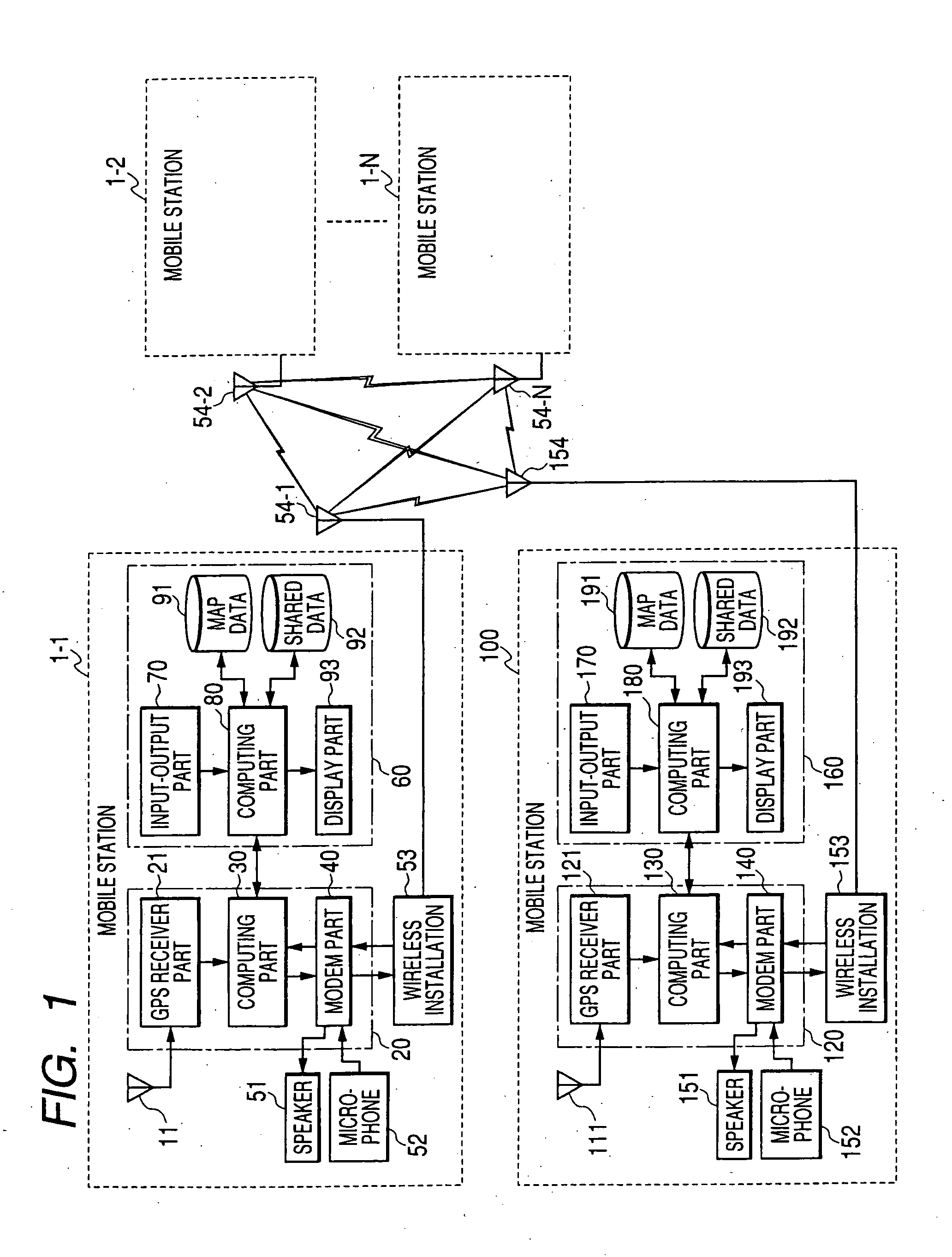
[0041]FIG. 1 is a block diagram showing a first preferred embodiment of a mobile unit information sharing system according to the invention.

[0042] In FIG. 1, mobile stations 1 (1-1, 1-2, . . . , 1-N) and a base station 100 conduct wireless communications via respective communication antennas 54 (54-1, 54-2, . . . 54-N) and 154.

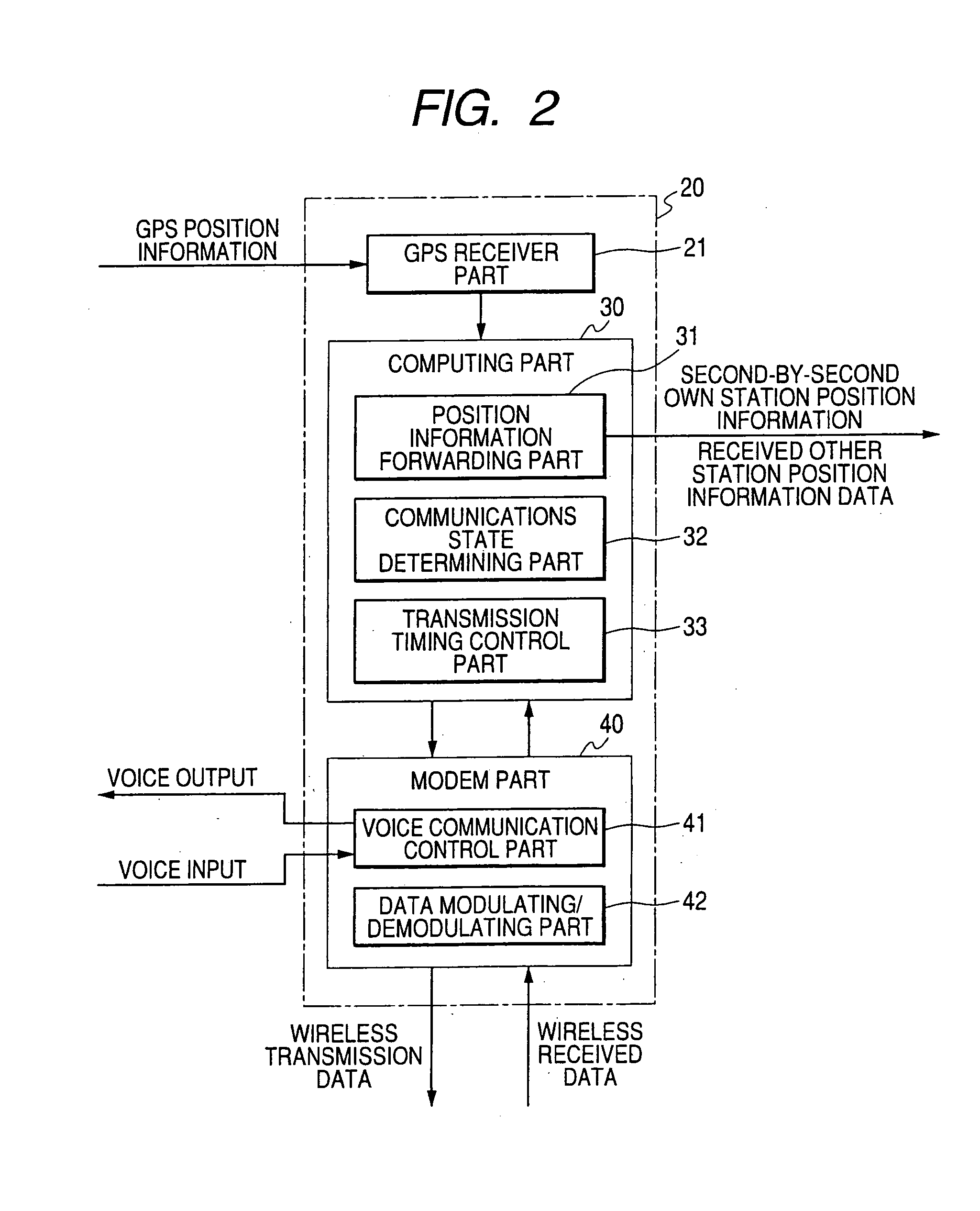
[0043] The mobile station 1, besides the communications antenna 54, is made up of a GPS antenna 11, a time-sharing synchronous wireless modem device 20, a speaker 51, a microphone 52, a wireless installation 53, and a position information display device 60. These will now be discussed in turn.

[0044] The GPS antenna 11 receives GPS position information and time information. Here, position information is information made up of the latitude, longitude, direction of movement and speed of movement of the own mobile station (hereinafter, own station). In the f...

second preferred embodiment

[0086]FIG. 8 is a view illustrating different position information transmission periods of a mobile unit information sharing system according to a second preferred embodiment of the invention.

[0087]FIG. 9 is a view illustrating position information transmission periods made variable in a mobile unit information sharing system according to the second preferred embodiment of the invention.

[0088] In FIG. 8 and FIG. 9, the reference numbers 2 and 3 denote the same things as in FIG. 5.

[0089] Whereas in the first preferred embodiment a case was discussed in which the regular position information transmission period was constant, in the second preferred embodiment, switching means for regular position information transmission period is provided in the computing part 30, and the regular position information transmission period can be varied in the middle of regular communications, as shown in FIG. 9.

[0090] As shown in FIG. 8, a shortened regular position information transmission period ...

third preferred embodiment

[0094]FIGS. 10A and 10B are views illustrating the transmission of image data in a mobile unit information sharing system according to a third preferred embodiment of the invention, FIG. 10A being a view showing the construction of a position information display device and FIG. 10B a view showing an image transmission packet for transmitting image information.

[0095] In FIG. 10A, the reference numbers 60, 70, 80 and 91 to 93 denote the same parts as in FIG. 3. The input-output part 70 is provided with image (for transmission) selecting means 73 for selecting an image for transmission and an image inputting part74 for inputting an image from a shot image storage medium, and the computing part 80 is provided with an image block division processing part 83 for dividing images into blocks for transmission and an image compressing part 84 for compressing images. Although the input-output part 70 has the basic period setting means 71 and the own station ID setting means 72 of FIG. 3 and t...


PUM


Abstract

A mobile unit information sharing system with which it is possible by wireless communications and without providing a communications control station to share not only voice data but also position information of multiple mobile stations and business information such as images formed in the course of business and instructions and the like. A base station and multiple mobile stations each, by a time-sharing synchronous wireless modem device, acquire position information for themselves and time information via a GPS antenna and transmit their station position information via a wireless installation using a wireless frequency common to all the stations and with timing determined, on the basis of the acquired time information, so that their station position information does not collide with position information transmissions from other stations.

Description

BACKGROUND OF THE INVENTION [0001] This invention relates to a mobile unit information sharing system wherein, among multiple mobile units (mobile stations) and a base station supervising the movements of the mobile units, position information of the mobile units is shared among the stations using a common wireless frequency. [0002] Mobile unit communication systems of related art wherein voice signals are transmitted and received using a common wireless frequency include individual mobile unit information management systems in which information on individual mobile units is managed by a central station. An example of this appears in Japanese Patent Laid-open Publication JP-A-2001-43500 (Patent Document 1). [0003] And in information sharing systems using wireless communications of related art, in communicating information such as the positions and activity states of multiple mobile units, and site images and so on, to avoid communication collisions and information bias, information ...

Claims


Application Information

Patent Timeline
Patent Type & Authority Applications(United States)
IPC IPC(8): H04Q7/20G01S5/00G01S19/48G08G1/13H04M11/00H04W4/02H04W4/06H04W8/08H04W28/00H04W64/00H04W74/02
CPCG01S5/0072G01S19/13H04W4/02H04W4/185
Inventor NONOYAMA, YASUMASAMEADA, YOSHIKO
Owner MITSUBISHI ELECTRIC CORP
Why Eureka
Try Eureka