Extended radius prosthesis and associated method

a prosthesis and extension radius technology, applied in the field of orthopaedics, can solve the problems of stress on joints or damage to joints in the body, wear and tear of cartilage, and damage to other connective tissues such as tendons or ligaments, and achieve the effect of simple shell rotation, reduced press fit, and simple shell rotation

Active Publication Date: 2006-01-05
DEPUY PROD INC
View PDF30 Cites 26 Cited by
  • Summary
  • Abstract
  • Description
  • Claims
  • Application Information

AI Technical Summary

Benefits of technology

[0022] Yet another technical advantage of the present invention is the ability of the present invention of the implant to permit simple rotation of the shell with a deep profile shell. For example, according to yet another aspect of the present invention an acetabular cup is provided with the outer periphery defined by a locus of points extending from an origin. Thus, the present invention provides for the simple rotation of a shell with a deep shell profile.
[0023] Yet another technical advantage of the present invention includes the ability to provide reduced press fit at the shell acetabulum interface for a deep profile shell. For example, according to yet another aspect of the present invention a shell is provided with a generally spherical shape including a first portion hemisphere and a second portion extending from the first por...

Problems solved by technology

The joints in the body are stressed or can be damaged in a variety of ways.
Over time, the normal use of a joint may wear down the cartilage and bring the moving bones in a direct contact with each other.
In contrast, in normal use, a trauma to a joint, such as the delivery of a large force, from an accident for, example, an automobile accident, may cause considerable damage to the bones...

Method used


Image

  • Extended radius prosthesis and associated method
  • Extended radius prosthesis and associated method
  • Extended radius prosthesis and associated method

Examples


Embodiment Construction

[0049] Embodiments of the present invention and the advantages thereof are best understood by referring to the following descriptions and drawings, wherein like numerals are used for like and corresponding parts of the drawings.

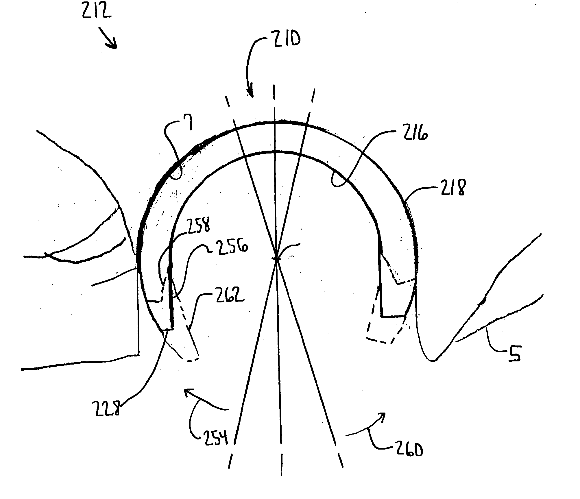
[0050] Referring now to FIG. 5, a prior art prosthesis in the form of a hip prosthesis is shown. The prosthesis 1 includes a hip cup or shell 2. The hip cup or shell 2 includes first hemispherical portion 3 from which extends a cylindrical portion 4. For proper fixation, the surgeon may prefer for all of the cylindrical portion 4 of the hip cup or shell 2 to extend below the acetabulum 5. If the orientation of the prosthesis 1 is required to be as shown as in FIG. 1, a portion, for example resected portion 6 of the acetabulum 5, must be removed.

[0051] Further, the positioning of the deep profile hip cup or shell 2 deep into the acetabulum 5 in order to obtain proper fixation of the shell or cup 2 to the acetabulum 5 may limit the range of motion for the pro...


PUM


Abstract

An acetabular shell for use in a hip prosthesis is provided. The shell includes a body having an inner periphery and a convex outer periphery and defining a cavity of the body. The outer periphery has a first portion defining a hemisphere and a second portion extending from the equator of the first portion in a converging direction. The second portion forms a rim opposed to the equator. The cavity is positioned within the rim.

Description

TECHNICAL FIELD OF THE INVENTION [0001] The present invention relates generally to the field of orthopaedics, and more particularly, to an implant for use in arthroplasty. BACKGROUND OF THE INVENTION [0002] A joint within the human body forms a juncture between two or more bones or other skeletal parts. The ankle, hip, knee, shoulder, elbow and wrist are just a few examples of the multitude of joints found within the body. As should be apparent from the above list of examples of joints, many of the joints permit relative motion between the bones. For example, the motion of sliding, gliding, hinge or ball and socket movements may be had by a joint. For example, the ankle permits a hinge movement, the knee allows for a combination of gliding and hinge movements and the shoulder and hip permit movement through a ball and socket arrangement. [0003] The joints in the body are stressed or can be damaged in a variety of ways. For example, the gradual wear and tear is imposed on the joints ...

Claims


Application Information

Patent Timeline
IPC IPC(8): A61F2/34A61F2/32A61F2/30A61F2/40
CPCA61B17/86A61F2310/00179A61F2/30771A61F2/32A61F2/34A61F2/36A61F2/3662A61F2/40A61F2/4609A61F2002/30324A61F2002/30332A61F2002/30787A61F2002/30805A61F2002/3081A61F2002/30822A61F2002/30827A61F2002/3085A61F2002/3208A61F2002/3216A61F2002/3233A61F2002/3266A61F2002/3401A61F2002/345A61F2002/3493A61F2002/3611A61F2002/365A61F2002/4619A61F2220/0033A61F2250/0036A61F2310/00017A61F2310/00023A61F2310/00029A61F2/30767A61F2002/3241
Inventor LEWIS, PAUL P.SCHNIEDERS, BARRY A.
Owner DEPUY PROD INC
Why Eureka
Try Eureka