
Operation apparatus, operation apparatus control method, program and computer readable information recording medium

a technology of operation apparatus and control method, which is applied in the direction of data conversion, instruments, memory adressing/allocation/relocation, etc., can solve the problems of difficulty in carrying out synchronous processing in a clock cycle level in a pipeline manner, difficulty in synchronizing the operation of clock cycle level, and ineffective utilization of the capacity of a data buffer

Inactive Publication Date: 2006-01-05
FUJITSU LTD
View PDF9 Cites 16 Cited by
  • Summary
  • Abstract
  • Description
  • Claims
  • Application Information

AI Technical Summary

Benefits of technology

[0023] By providing the sharable double buffer as mentioned above, it is possible to effectively reduce the required number of data buffers, and as a result, it is possible to solve a problem from an increased required area in a semiconductor chip for providing many data buffers, since the required total number of the data buffers can be thus reduced.
[0025] By employing such a configuration according to the present invention, the above-mentioned first and second problems can be solved, i.e., it is possible to enable selection between a mode of data transfer using a ‘path passing through a buffer’ and another mode using a ‘path not passing through a buffer’, flexibly for each particular situation according to the contents of an application to execute, and also, it becomes possible to achieve a configuration by which a capacity of a data buffer can be effectively utilized.

Problems solved by technology

This is because, when the alternate buffer is inserted, operation timing may be differed problematically.
In other words, assuming that processing in a feedback manner is included in which the operation apparatus A further carries out processing in a step of n+1 in a last part of the processing, the algorithm may break down due to such a timing error.
However, since data units to carry out are different therebetween, it is difficult to carry out the processing synchronously in a clock cycle level in a pipeline manner.

Method used


Image

  • Operation apparatus, operation apparatus control method, program and computer readable information recording medium
  • Operation apparatus, operation apparatus control method, program and computer readable information recording medium
  • Operation apparatus, operation apparatus control method, program and computer readable information recording medium

Examples


first embodiment

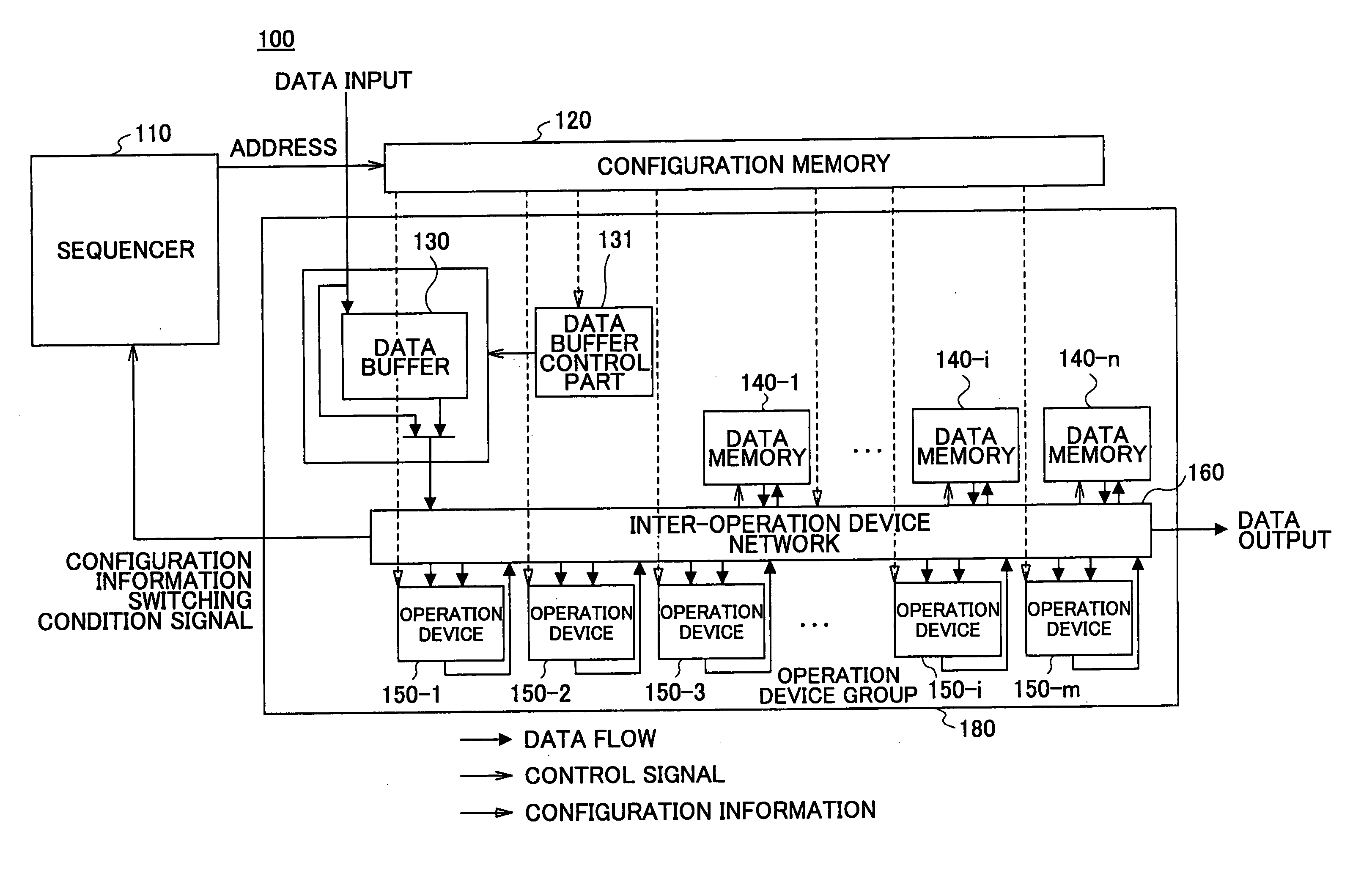
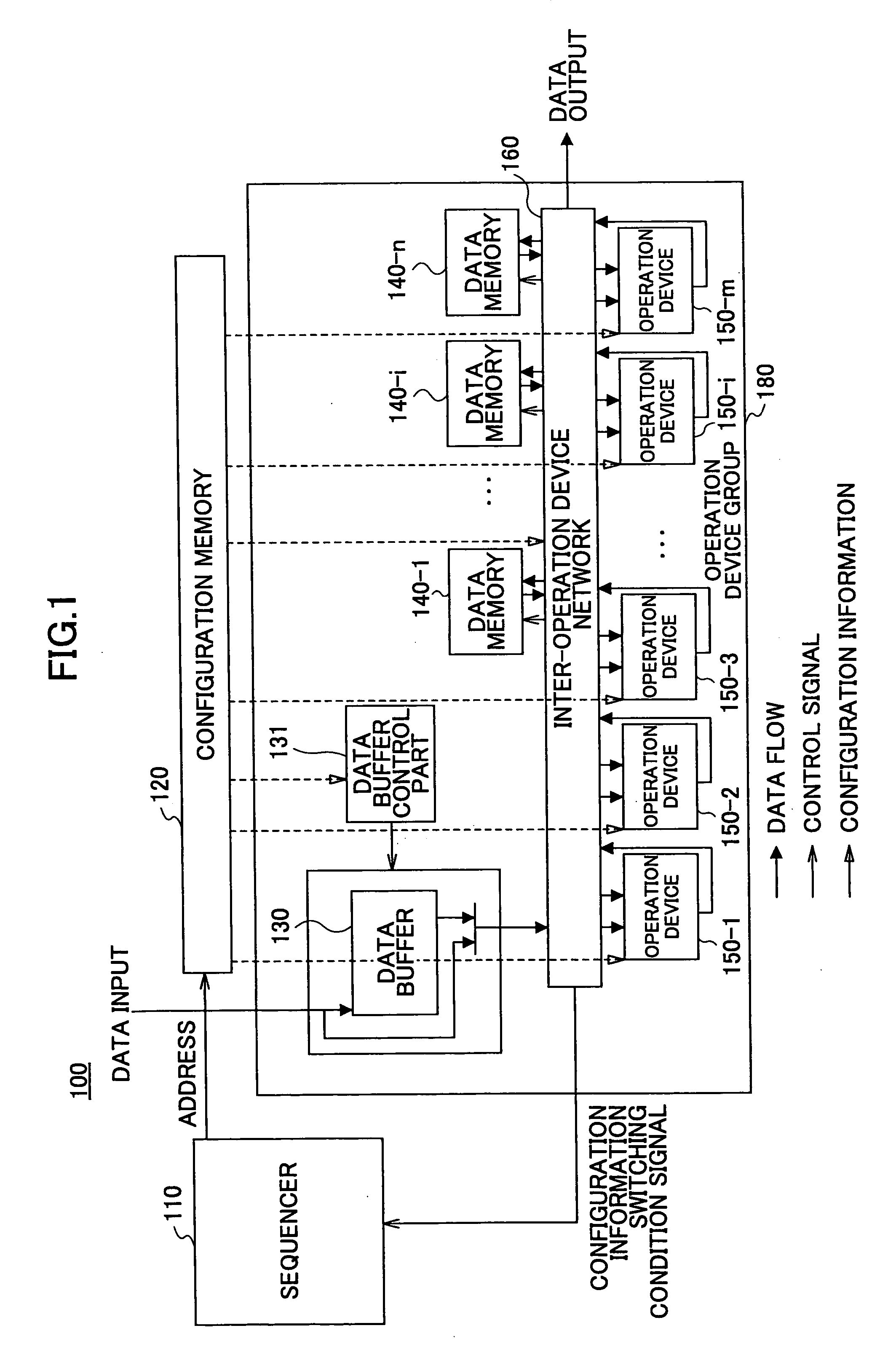
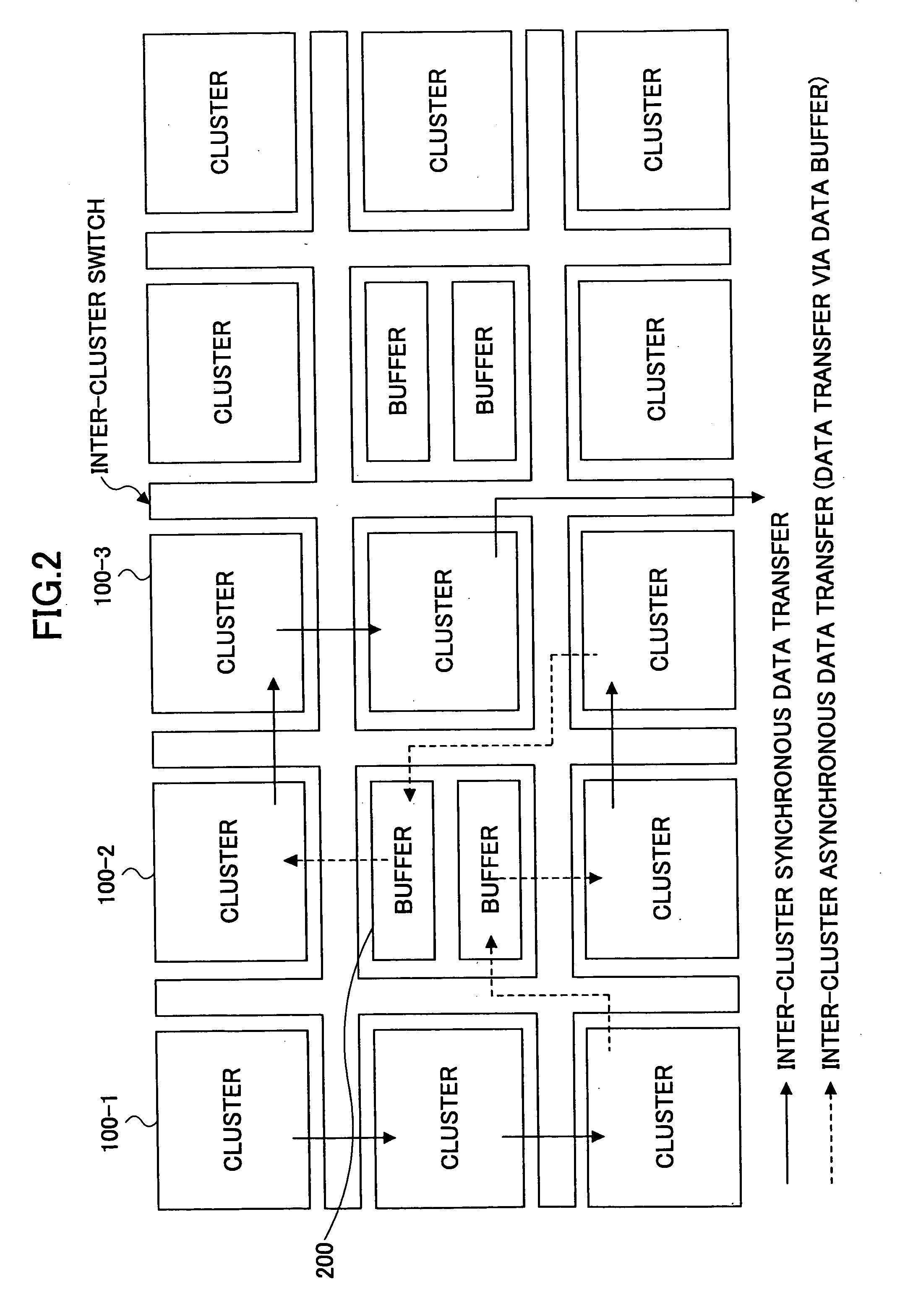
[0054]FIG. 3 shows an operation apparatus according to the present invention. As shown, in the operation apparatus according to the present embodiment, a plurality of clusters 100-1, 100-2, 100-3, . . . (which may be generally referred to as simply ‘cluster(s) 100’, hereinafter) are electrically connected mutually through paths indicated by arrows, respectively. Each cluster 100 includes, as mentioned above, an operation device group 180 including many operation devices (see FIG. 4), a configuration memory 120 storing therein configuration information for enabling execution of various sorts of operation processing by setting respective states of these operation devices so as to flexibly change configurations thereof, and a sequencer 110 which provides an instruction to select information from among the configuration information stored in the configuration memory 120 to actually apply to the operation device group 180.

[0055] According to the present embodiment, a communication networ...

third embodiment

[0086] In the third embodiment, the configuration information shown in FIG. 11B includes, as shown, two sets of configuration information corresponding to the respective two data buffer parts (280-1 and 280-2) shown in FIG. 11A. That is, for each of the two data buffer parts, an ‘automatic sending mode’ setting field, an ‘input data size’ information field and an ‘output data size’ information field are provided. As mentioned above, since a ‘buffer usage’ setting field is not necessary, it is omitted in this case.

fifth embodiment

[0087] In this example, as shown in FIG. 2, the data buffer clusters 200 are disposed in the center of the other plurality of clusters 100. However, it is also possible to dispose the data buffer clusters 200 also in the periphery of the other clusters 100 accommodating the operation device groups. In such a case, the data buffers of the data buffer clusters 200 may be used as buffers for fetching data from external memories. Such an example will be described as a fifth embodiment later.

[0088]FIG. 12 shows a configuration of a reconfigurable operation apparatus according to a fourth embodiment of the present invention. Also this embodiment is advantageous for solving the above-mentioned second problem. However, the same as in the example of FIG. 6, an inter-cluster data transfer network is configured not by a crossbar but by electric wires 198 and switches 195, 199. Further, the same as in the example of FIG. 9, the data buffer part 135 is not provided in each cluster 100 accommodat...


PUM


Abstract

An operation apparatus includes a sequencer controlling states of a plurality of operation devices and a configuration memory storing therein configuration information as setting information for each state in the operation device. In the operation apparatus, a path which requires a data buffer and another path which requires no such a data buffer are provided for inputting data to the operation device, a data buffer control part is provided for controlling selection from these two paths and operation of the data buffer, and contents of path selection and operation control of the data buffer carried out by the data buffer control part are set according to the configuration information.

Description

CROSS-REFERENCE TO RELATED APPLICATIONS [0001] This application is based upon and claims priority of Japanese Patent Application No. 2004-194797, filed on Jun. 30, 2004, the contents being incorporated herein by reference. BACKGROUND OF THE INVENTION [0002] 1. Field of the Invention [0003] The present invention relates to an operation apparatus, an operation apparatus control method, a program and a computer readable information recording medium, and, in particular, to a reconfigurable operation apparatus by which various sorts of processing are made to carry out as a result of the configuration thereof being dynamically changed, a control method therefor, a program including instructions for carrying out the method and a computer readable information recording medium storing therein the program. [0004] 2. Description of the Related Art [0005] For example, Japanese Laid-open Patent Application No. 2001-312481 discloses an operation apparatus having reconfigurable operation devices i...

Claims


Application Information

Patent Timeline
IPC IPC(8): G06F12/00
CPCG06F15/7867G06F9/38G06F15/163
Inventor SAITO, MIYOSHIFUJISAWA, HISANORIKASAMA, ICHIROKAWANO, TETSUOIMAFUKU, KAZUAKIFURUKAWA, HIROSHIURIU, SHIROWAKAYOSHI, MITSUHARU
Owner FUJITSU LTD
Learn More