Flow transducer and method

a technology of flow transducer and flow control, applied in the direction of volume/mass flow measurement, measurement device, instrument, etc., can solve the problem of disadvantage of transit-time transducer, and achieve the effect of simplifying its installation

Inactive Publication Date: 2006-01-12
HYBRID ELECTRONICS AUSTRALIA +1
View PDF9 Cites 14 Cited by
  • Summary
  • Abstract
  • Description
  • Claims
  • Application Information

AI Technical Summary

Benefits of technology

[0010] The flow transducer may include a head that is rotationally symmetrical about an axis perpendicular to its diaphragm and relative to the direction of fluid flow to make the transducer insensitive to rotation. In some applications, it is desirable that the flow transducer be sensitive to magnitude of flow but not to direction of flow. In such applications, the flow transducer preferably is arranged such that it is insensitive to orientation of the fluid flow and to orientation of any pipe or channel containing the flowing fluid. Rotational insensitivity of the transducer may simplify its installation into the fluid stream, because an adjustment of transducer orientation may not be required. The flow transducer, may be arranged such that it can be inserted into a channel or pipe that is incompletely filled with fluid, and can be used to measure the speed of flow, including an absence of flow and / or absence of fluid.

Problems solved by technology

The transit-time transducer has a disadvantage of requiring access to the fluid stream in two places: a site where thermal energy is injected, and a downstream site for temperature-sensing.

Method used


Image

  • Flow transducer and method
  • Flow transducer and method
  • Flow transducer and method

Examples


Embodiment Construction

[0019] Preferred embodiments of the present invention will now be described with reference to the accompanying drawings wherein:

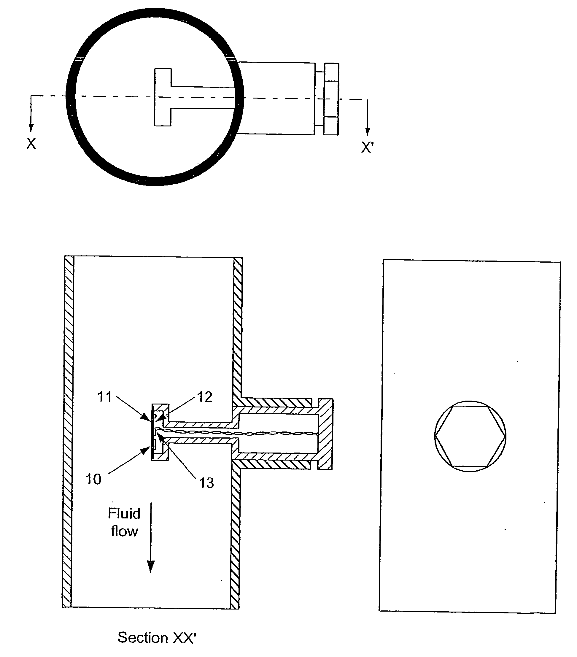
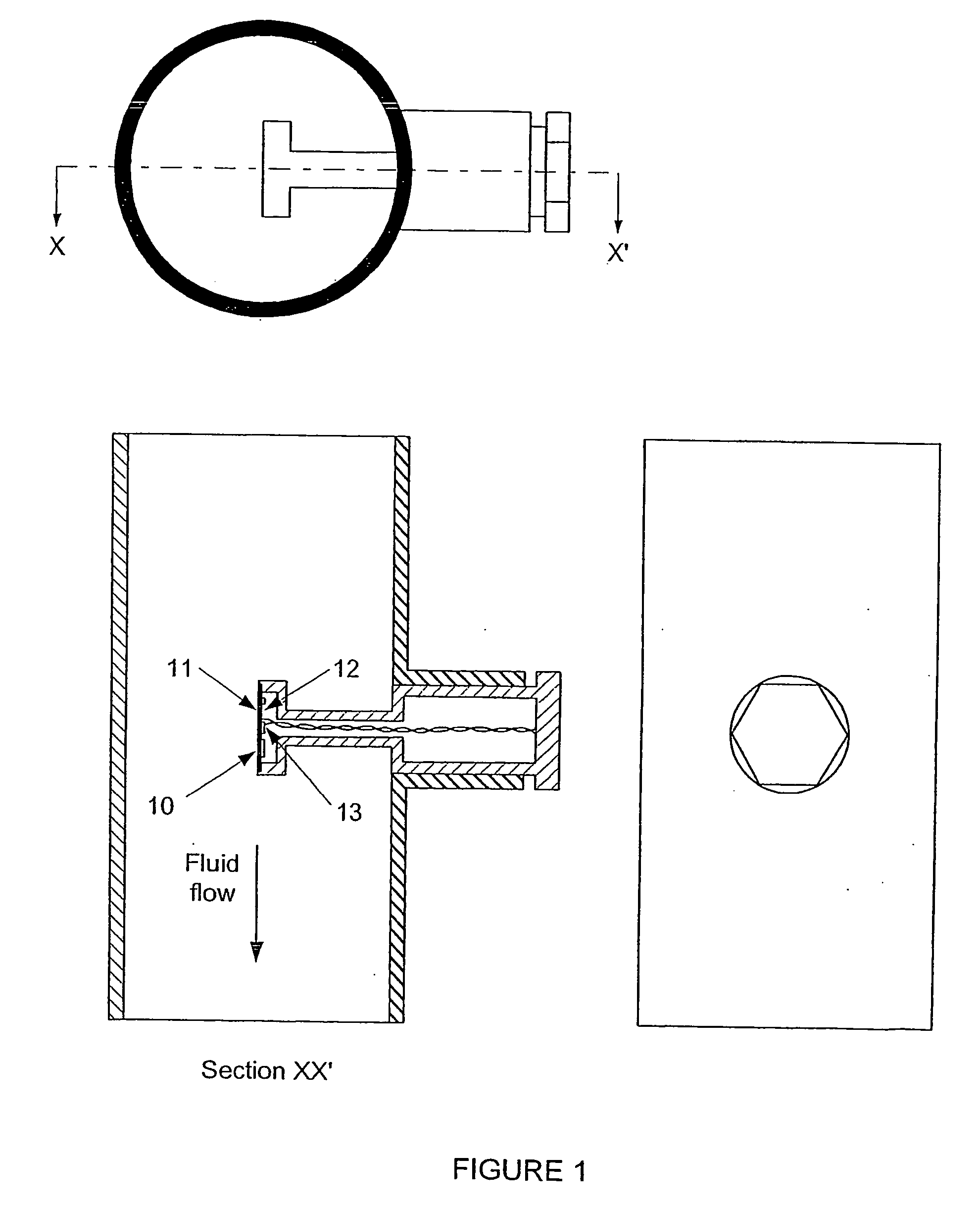
[0020]FIG. 1 illustrates a sensor head inserted into a pipe carrying fluid whose flow-rate is to be measured;

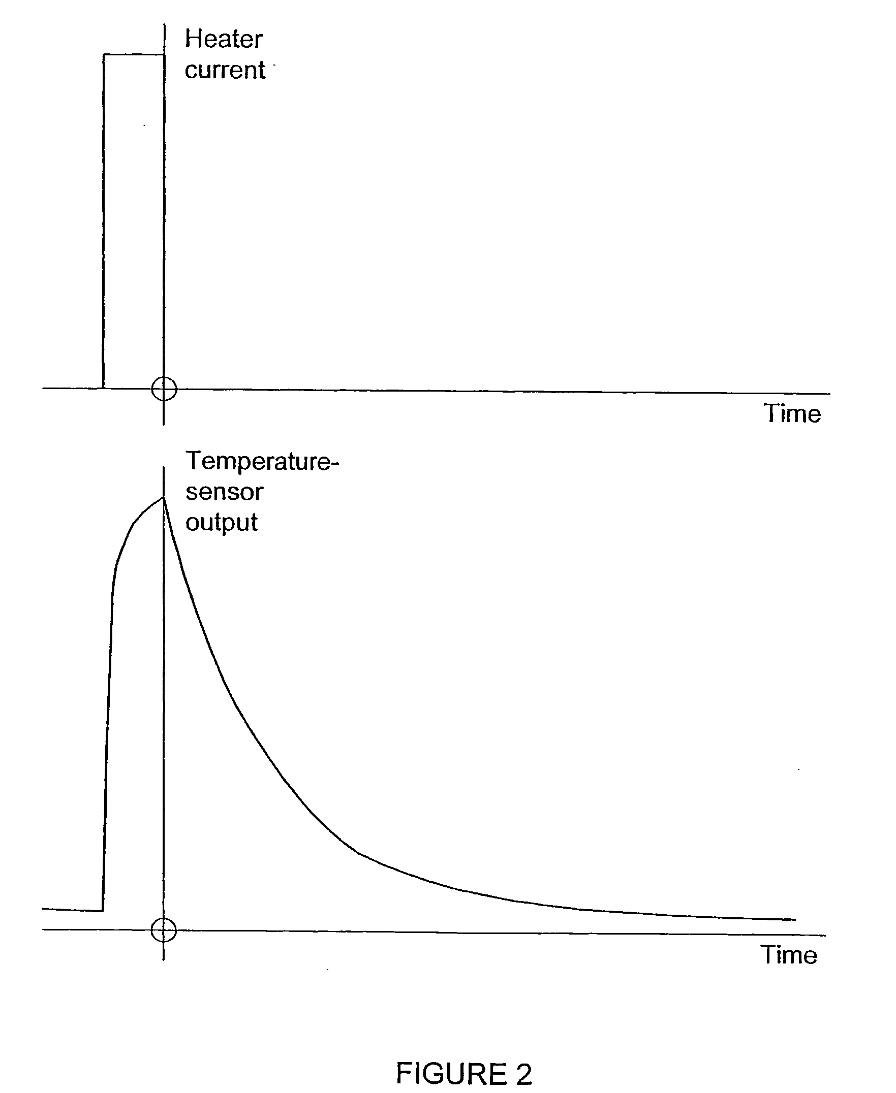
[0021]FIG. 2 shows a waveform associated with temperature response in relation to an applied heat-pulse;

[0022]FIG. 3 shows a decaying temperature response and illustrates a method of determining flow rate by measuring decay at a fixed time; and

[0023]FIG. 4 shows a decaying temperature response and illustrates a further method of determining flow rate by measuring decay at a fixed threshold-level.

[0024] Referring to FIG. 1 the sensor head includes a thin diaphragm 10, typically of metal such as stainless steel or titanium (refer Australian Patent Applications 2002 952 359 and 2003 900 272). One side 11 of diaphragm 10 is in contact with the fluid, and may be termed the fluid face. Diaphragm 10 acts as a substrate for a thick-film hybrid integrated...


PUM


Abstract

A transducer is disclosed for sensing flow of a fluid. The transducer includes means for applying a heat pulse to the fluid and at least one temperature sensor. The temperature sensor is adapted to detect a decaying response to the heat pulse to provide an indication of the flow. The decaying response may be detected by comparing measured voltages at a set moment in time or by comparing measured times at a set voltage threshold. A method for sensing flow of a fluid is also disclosed.

Description

CROSS REFERENCE TO RELATED APPLICATIONS [0001] This invention is related to and claims priority from Australian Patent Application No. 2002952330, filed Oct. 29, 2002, entitled Flow Transducer And Method; and PCT Application No. PCT / AU2003 / 001416, filed Oct. 24, 2003, entitled Flow TransducerAnd Method, which are incorporated herein by reference.FIELD OF THE INVENTION [0002] The present invention relates to a flow transducer. In particular the invention relates to a transducer for measuring rate of flow of a fluid. It is desirable to provide a flow transducer in the form of a single or self contained element, monitor or assembly, that is capable of being inserted into a fluid stream. Throughout the specification, the term “fluid” is to be interpreted to include both liquid and gaseous forms of fluid. BACKGROUND OF THE INVENTION [0003] Various calorimetric flow transducers have been proposed previously. One type is represented by a hot-wire anemometer, in which a thin wire is heated ...

Claims


Application Information

Patent Timeline
Patent Type & Authority Applications(United States)
IPC IPC(8): G01F1/708G01F1/698
CPCG01F1/6986
Inventor BREEN, DONNELLY JAMESBERRYMAN, WALTER HENRY
Owner HYBRID ELECTRONICS AUSTRALIA
Why Eureka
Try Eureka