Linear actuator with releasably interlocking bands

a linear actuator and interlocking technology, applied in the field of linear actuators, can solve the problems of column collapsing, horizontal and vertical bands simply resting, and column structural integrity likely to be compromised, so as to prevent rotation

Active Publication Date: 2006-01-12
TION LAFOREST
View PDF16 Cites 10 Cited by
  • Summary
  • Abstract
  • Description
  • Claims
  • Application Information

AI Technical Summary

Benefits of technology

[0049] In one embodiment, said linear actuator further comprises a first anti-rotation member attached to either one of said structural and fastening bands and engaging a second anti-rotation member attached to said frame, wherein said structural and fastening bands are prevented from rotating.
[0050] In one embodiment, said teeth are also first anti-rotation members that cooperate with second anti-rotation members provided on said frame in spaced-apart fashion around said central axis, with at least one of said teeth engaging a corresponding space defined between two said second anti-rotation members at all times, whereby said structural and fastening bands are prevented from rotating.

Problems solved by technology

One problem associated to the push actuator of the Gagnon patent is that the horizontal and vertical bands simply rest on each other without being interlocked in any way.
However, the structural integrity of the column is likely to be compromised if a force is exerted on the column perpendicularly to its central axis.
Indeed, in such a case, the two intertwined bands of the column may accidentally disengage themselves from one another, which would lead to the column collapsing.
Indeed, the scissor-type linkages will only allow the load being carried to be moved in the direction of the axis of the push actuator.

Method used


Image

  • Linear actuator with releasably interlocking bands
  • Linear actuator with releasably interlocking bands
  • Linear actuator with releasably interlocking bands

Examples


Embodiment Construction

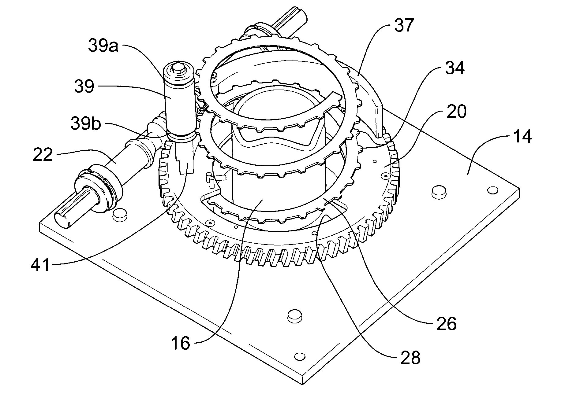
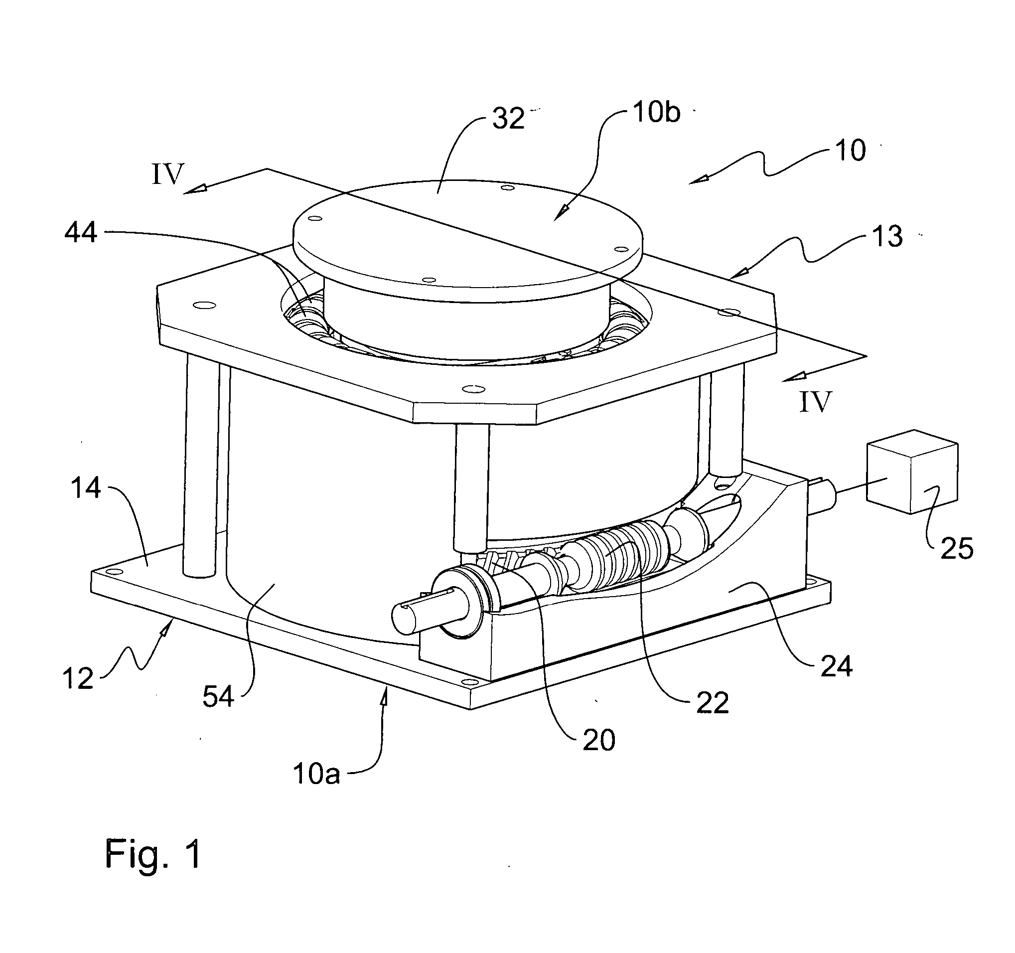
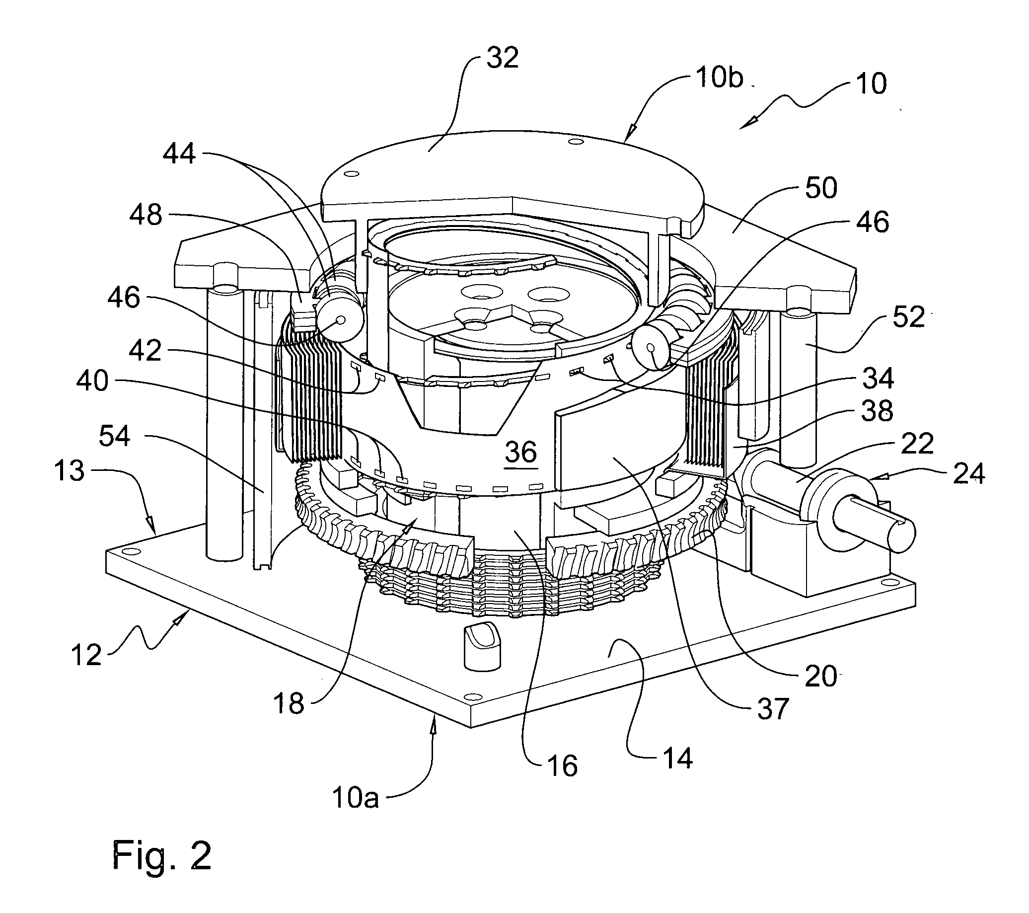
[0065]FIGS. 1-8 show a linear actuator 10 according to one embodiment of the present invention, for use in exerting pushing and / or pulling actions on outer elements. One example of an application of the linear actuator 10 of the present invention, to which it is not limited, is for use as a vertical pushing member similarly to the push actuator described in the Gagnon patent discussed in the Background of the Invention section. Other alternate uses of the linear actuator will be described later on.

[0066] Linear actuator 10 defines opposite first and second ends 10a, 10b and an intermediate portion between first and second ends 10a, 10b wherein its first and second bands are being releasably linked or interconnected to each other, as described hereinafter. Linear actuator 10 further defines a central axis 11 extending between first and second ends 10a, 10b and comprises a frame 13 including a base 12 formed of a bottom, ground-resting plate 14 and an upstanding cylindrical hub 16 ca...


PUM


Abstract

The linear actuator comprises an elongated first band wound in helical form about a central axis and capable of taking a retracted position and an extended position with its turns spaced from one another in the direction of the central axis, and first fasteners carried by the first band and longitudinally disposed therealong. The linear actuator also comprises an elongated second substantially flat band wound on itself, with its turns substantially transversely parallel to the central axis, and capable of taking a retracted, spiral position with its turns nested within one another and an extended position with its turns forming a helix around the central axis and generally equally radially spaced therefrom to form a telescopic column, the first and second bands, when in retracted position, in respective locations so as to clear each other. Second fasteners are carried by the second band and longitudinally disposed therealong, the second fasteners capable of cooperating with the first fasteners to releasably interlock the first and second bands. A spacer successively spaces the turns of the first band. A powered drive causes relative rotation on one hand of the first and second bands and on the other hand of the spacer about the central axis. Guide means guide the turns of the second band towards the turns of the first band to releasably interlock the first and second fasteners. A retaining member retains the first and second fasteners in interlocked fashion in the telescopic column.

Description

FIELD OF THE INVENTION [0001] The present invention relates to a linear actuator, and more particularly to a linear actuator with releasably interlocking bands that form a retractable telescopic column. BACKGROUND OF THE INVENTION [0002] U.S. Pat. No. 4,875,660 issued in 1989 to the inventors Pierre GAGNON and Pierre LAFOREST (the inventor of the present invention), hereafter the “Gagnon patent” which is hereby incorporated to the present specification by way of reference, shows a push actuator to be used as a pushing device, for example instead of a hydraulic cylinder. The push actuator of the Gagnon patent has the advantage of requiring less space than conventional hydraulic cylinders when in a contracted position, due to the fact that no concentric column portions have to be stored within each other. Also, it can support very heavy loads, since it forms a cylindrical column when in an extracted position, without any concentric portions as with a hydraulic cylinder, and this verti...

Claims


Application Information

Patent Timeline
Patent Type & Authority Applications(United States)
IPC IPC(8): F16H1/16
CPCY10T74/19828B66F11/00
Inventor LAFOREST, PIERRE
Owner TION LAFOREST
Why Eureka
Try Eureka