
Enveloping worm transmission

Inactive Publication Date: 2006-01-12
FLEYTMAN YAKOV
View PDF26 Cites 20 Cited by
  • Summary
  • Abstract
  • Description
  • Claims
  • Application Information

AI Technical Summary

Benefits of technology

[0020] In this invention each side of a thread: concave surface and a convex surface is able to transmit torque, that is distinguished from double enveloping gearing. In addition, by transmitting torque t

Problems solved by technology

Enveloping worm transmission with teeth surface generated by profile of a thread where an enveloping worm having at least one screw thread that is engaged by at least one tooth of said worm gear has limitations to transferring torque mostly by concave surface of the worm thread.

Method used


Image

  • Enveloping worm transmission
  • Enveloping worm transmission
  • Enveloping worm transmission

Examples


Embodiment Construction

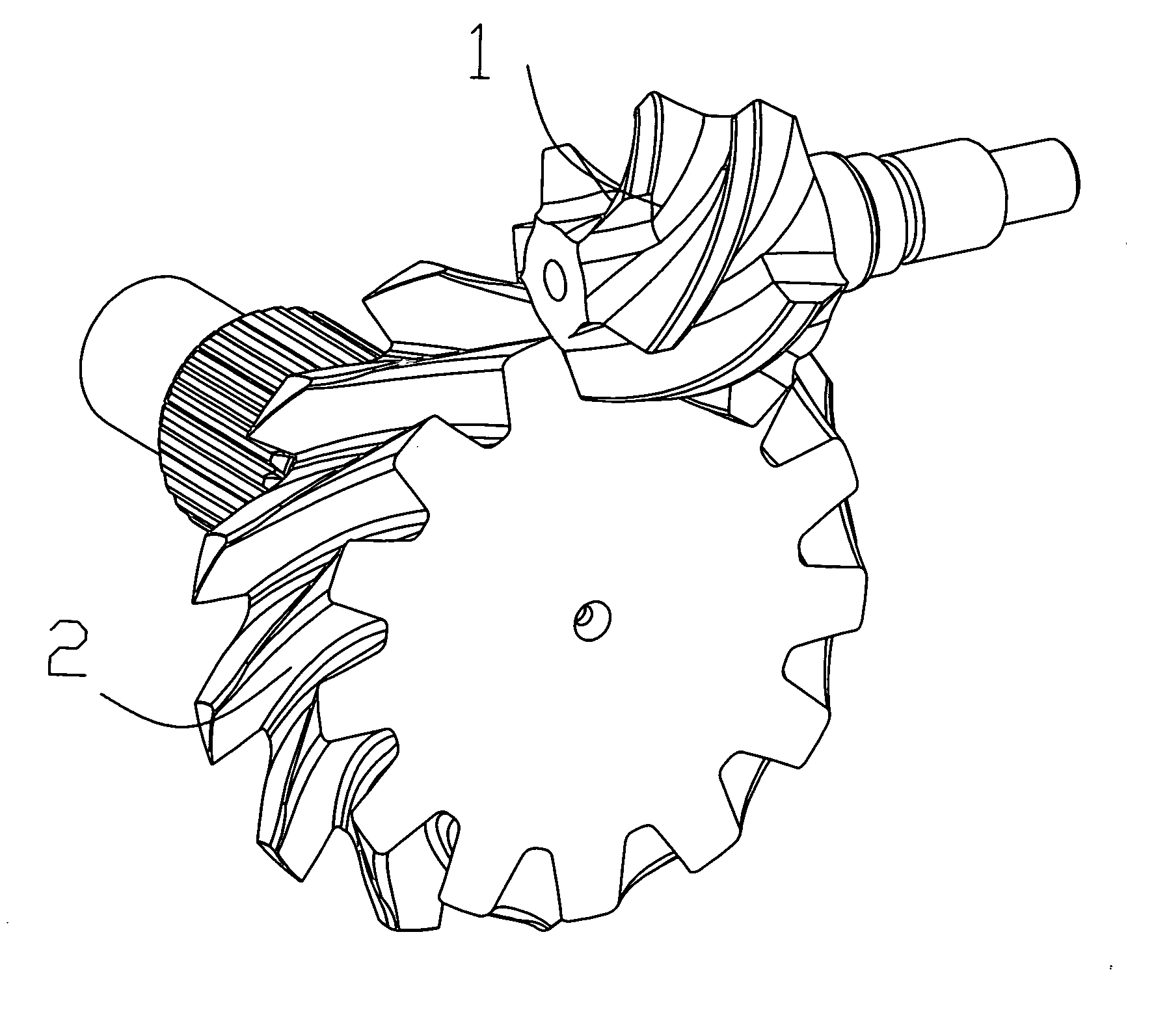
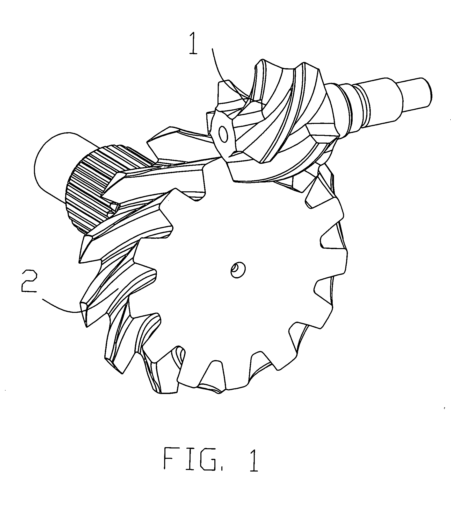
[0037] The following discussion relating to FIGS. 1-13 provides a detailed description of the unique enveloping worm gear transmissions that can be utilized with the present invention.

[0038] More torque capacity is the main advantage for using the enveloping worm transmission. The enveloping worm mostly has a rolling action contact relationship with the teeth of the worm gear that provides an increased efficiency. With standard double enveloping worm designs, having more than one thread and a large enveloping angle, the inability to assemble the worm and worm gear was considered a major obstacle. With the enveloping worm and worm gear of the present invention, the enveloping worm and worm gear are easily assembled by properly orienting the worm thread and worm teeth. According to the present invention, the greater enveloping angle for one revolution of a worm thread permits the use of worm gear teeth without undercut portions.

[0039] Referring now to the drawings, one embodiment of...


PUM


Abstract

An enveloping worm transmission is provided with a unique enveloping worm and worm gear with modified enveloping worm thread surfaces. Enveloping worm has general arrangements with worm gear on the face of worm gear. This invention offers combinations of enveloping worm with mating face worm gear where worm gear axis intersected, crossed or parallel to enveloping worm axis. The enveloping worm gear transmission is more efficient, quite and compact than conventional gear systems which have typically been used in power applications. The enveloping worm transmission of the present invention is easy manufacturing.

Description

[0001] This is a continuation-in-part of Ser. No. 10 / 435,143 filed May 9, 2003FIELD OF THE INVENTION [0002] An enveloping worm transmission is suitable for the transformation of motion and power between an enveloping worm and a worm gear wherein the axis of the worm gear and the worm may be crossed or intersected. The enveloping worm transmission includes one or multi-thread enveloping worm engaged with a worm gear. One potential application for this transmission is a helicopter rotor drive. As is known, one of the biggest problems, associated with helicopter rotor drives is noise. When compared to conventional spiral bevel gear transmissions, worm / gear type transmissions generate minimum noise. However, low efficiency and torque capacity associated with prior art worm / worm gear transmissions prevented their use in helicopter power transmission systems. [0003] Certain applications may be outside of these fields, like automobile gearboxes, turbine gearboxes, power windows, doors or s...

Claims


Application Information

Patent Timeline
IPC IPC(8): F16H1/16F16H1/12F16H55/22
CPCF16H1/06F16H1/12Y10T74/19828F16H1/16F16H55/22F16H1/125
Inventor FLEYTMAN, YAKOV
Owner FLEYTMAN YAKOV
Features
  • Generate Ideas
  • Intellectual Property
  • Life Sciences
  • Materials
  • Tech Scout
  • Unparalleled Data Quality
  • Higher Quality Content
  • 60% Fewer Hallucinations
Learn More