
Lock-up device and control method for lock-up device

a technology of lock-up device and control method, which is applied in the direction of fluid couplings, gearings, instruments, etc., can solve the problems of discontinuing favorable slip control and insufficient lock-up capacity

Active Publication Date: 2012-06-07
AISIN AW CO LTD
View PDF5 Cites 9 Cited by
  • Summary
  • Abstract
  • Description
  • Claims
  • Application Information

AI Technical Summary

Benefits of technology

[0009]In addition, the hydraulic pressure command value may include a hydraulic pressure command feedforward term corresponding to the drive source torque in the case where the accelerator operation amount variation amount is in the predefined range, the hydraulic pressure command value may include a hydraulic pressure command feedforward term corresponding to the predicted drive source torque in the case where the accelerator operation amount variation amount becomes more than the upper limit of the range because of an increase in accelerator operation amount, and a correction value for promoting an increase in torque capacity of the lock-up clutch may be added to the hydraulic pressure command value over a predetermined time since the accelerator operation amount variation amount becomes more than the upper limit of the range because of an increase in accelerator operation amount. Consequently, it is possible to better match the torque capacity of the lock-up clutch with the torque actually being output from the drive source by responsively supplying a hydraulic pressure corresponding to the hydraulic pressure command value from the hydraulic unit to the lock-up clutch when the accelerator operation amount variation amount becomes more than the upper limit of the range because of an increase in accelerator operation amount during execution of the slip control.
[0010]Further, the hydraulic pressure command value setting unit may derive the predicted drive source torque corresponding to the accelerator operation amount to set the hydraulic pressure command value corresponding to the predicted drive source torque such that the difference in rotational speed becomes the target slip speed in the case where the accelerator operation amount variation amount becomes less than a lower limit of the range because of a decrease in accelerator operation amount. That is, in the case where the accelerator operation amount variation amount becomes less than the lower limit of the range because of a decrease in accelerator operation amount during execution of the slip control, the response or the accuracy in derivation of the drive source torque performed by the drive source control unit may be degraded to result in overestimation of the drive source torque. Then, if the hydraulic pressure command value were set in correspondence with the drive source torque in such a case, the torque capacity of the lock-up clutch might be excessive to discontinue favorable slip control. In the lock-up device, in contrast, in the case where the accelerator operation amount variation amount becomes less than the lower limit of the range during execution of the slip control, the predicted drive source torque corresponding to the accelerator operation amount which can be acquired more responsively, in place of the drive source torque from the drive source control unit, is derived to set the hydraulic pressure command value for the hydraulic unit in correspondence with the predicted drive source torque. Then, it is possible to better match the hydraulic pressure command value with the torque actually being output from the drive source. Consequently, according to the lock-up device, it is possible to continue favorable slip control even if the accelerator operation amount decreases during execution of the slip control.
[0011]In addition, a correction value for promoting a decrease in torque capacity of the lock-up clutch may be subtracted from the hydraulic pressure command value over a predetermined time since the accelerator operation amount variation amount becomes less than the lower limit of the range because of a decrease in accelerator operation amount. Consequently, it is possible to better match the torque capacity of the lock-up clutch with the torque actually being output from the drive source by responsively supplying a hydraulic pressure corresponding to the hydraulic pressure command value from the hydraulic unit to the lock-up clutch when the accelerator operation amount variation amount becomes less than the lower limit of the range because of a decrease in accelerator operation amount during execution of the slip control.
[0013]According to the control method, it is possible to continue favorable slip control without causing high-rpm idling of the drive source due to underestimation of the drive source torque even if the accelerator operation amount increases during execution of the slip control in which the hydraulic unit is controlled such that the difference in rotational speed between the input member and the input shaft of the speed change device becomes the target slip speed corresponding to the state of the vehicle through half engagement of the lock-up clutch.

Problems solved by technology

When the throttle opening of the engine (accelerator operation amount) is increased in accordance with an accelerator operation during execution of the slip control discussed above, however, the engine torque may be underestimated to conversely result in an insufficient lock-up capacity (torque capacity of the lock-up clutch) because of a response delay in calculation of the engine torque or a reduction in accuracy in calculation of the engine torque.
Then, if the lock-up capacity becomes insufficient with the throttle opening increasing during execution of the slip control, high-rpm idling of the motor may occur to discontinue favorable slip control.
However, Japanese Patent Application Publication No. 2006-29464 mentioned above does not at all consider such a situation where the lock-up capacity becomes insufficient with the accelerator operation amount increasing during execution of the slip control.

Method used


Image

  • Lock-up device and control method for lock-up device
  • Lock-up device and control method for lock-up device
  • Lock-up device and control method for lock-up device

Examples


Embodiment Construction

[0022]An embodiment of the present invention will be described below.

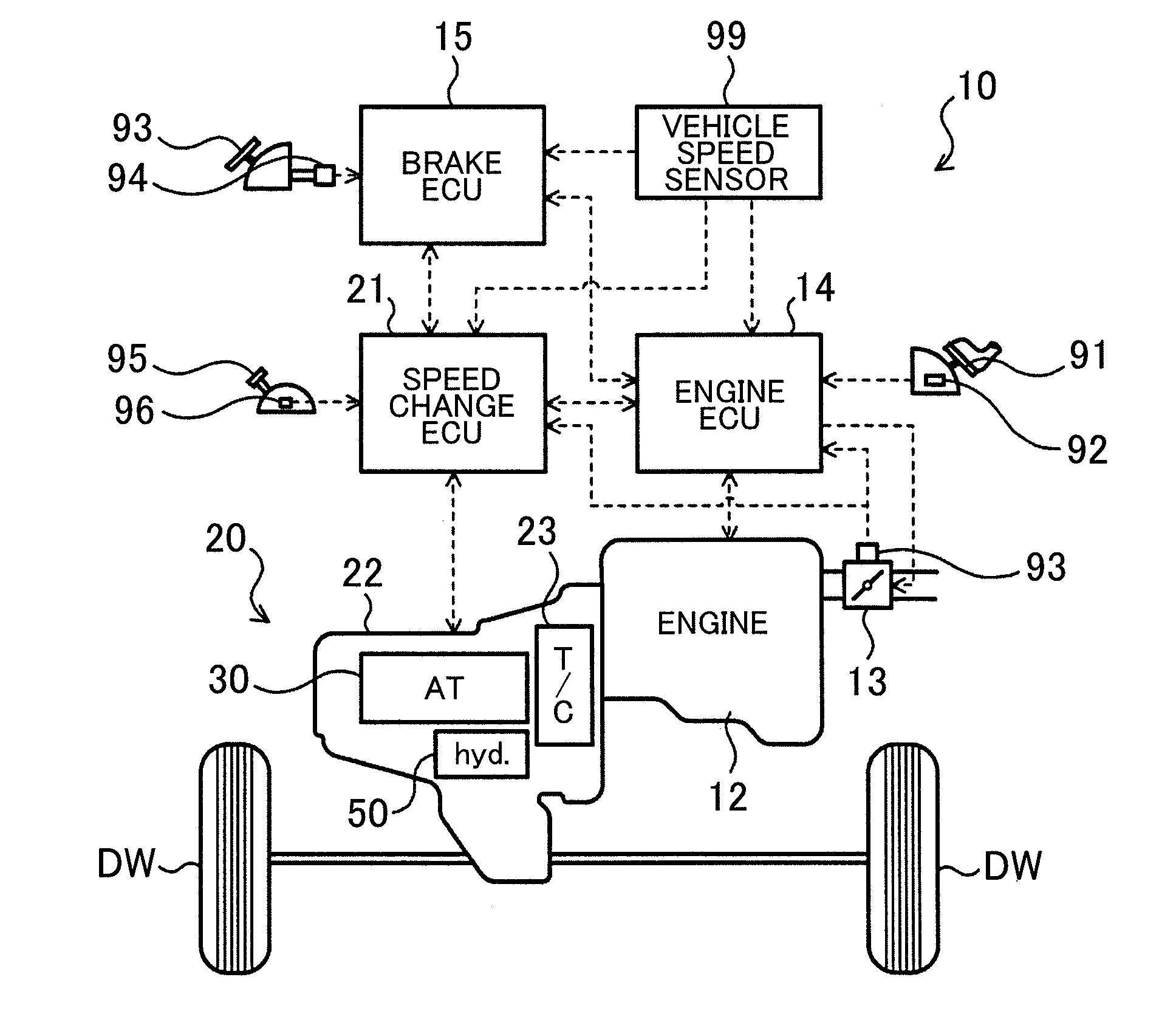
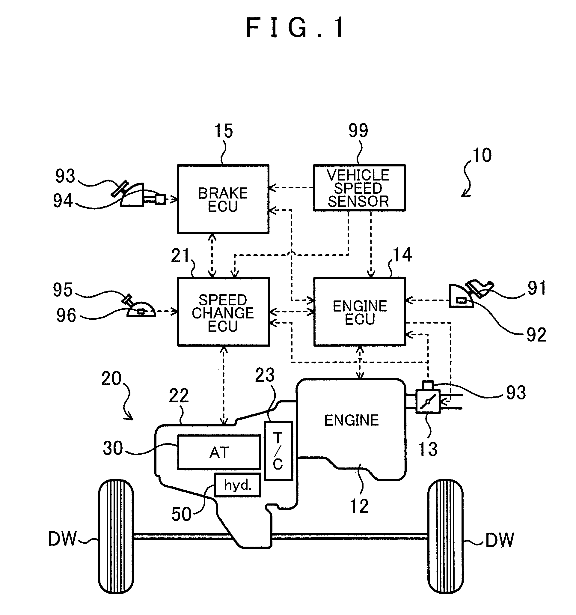
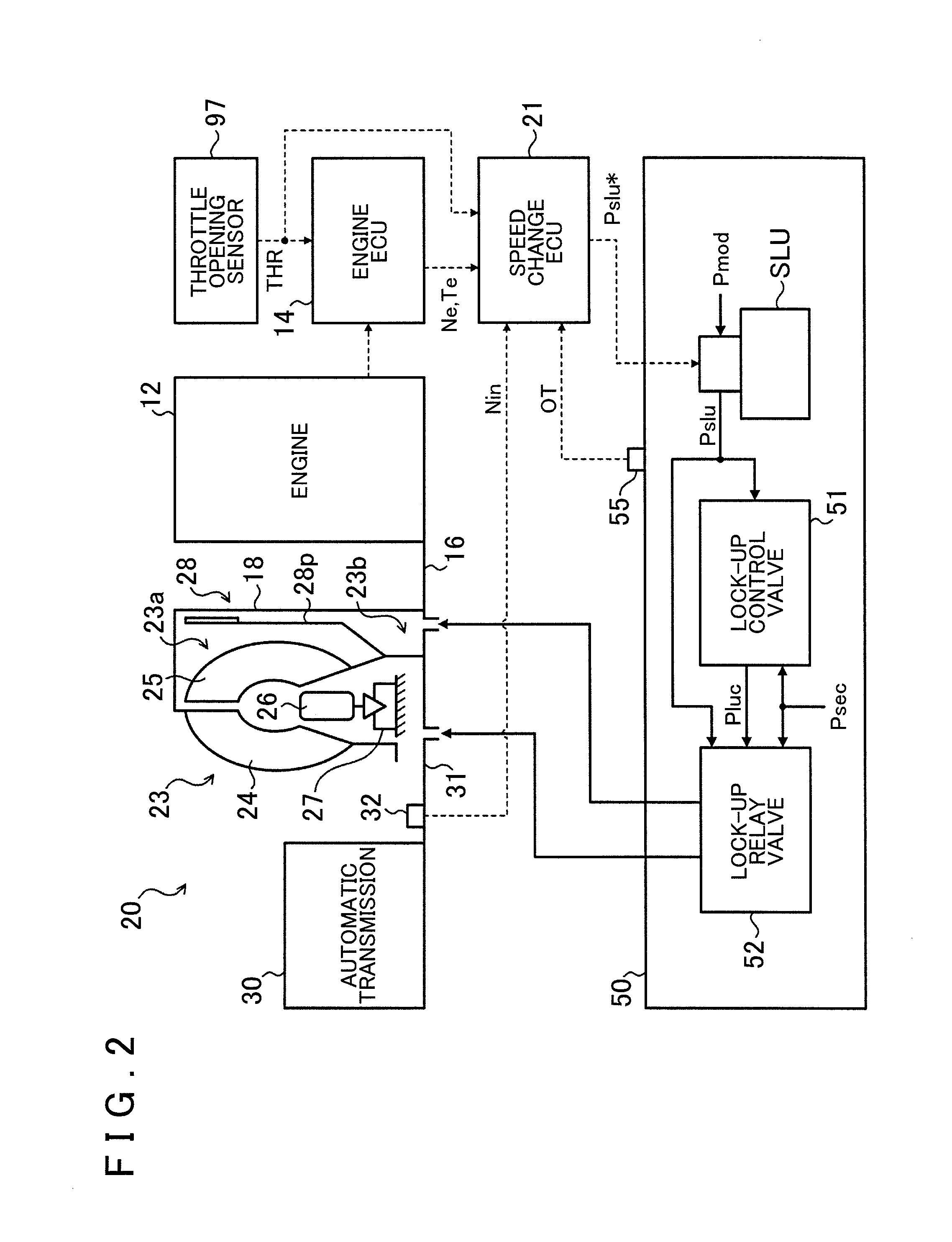
[0023]FIG. 1 shows a schematic configuration of an automobile 10 which is a vehicle incorporating a power transfer device 20 including a lock-up device according to an embodiment of the present invention. FIG. 2 shows a schematic configuration of the power transfer device 20. The automobile 10 shown in FIG. 1 includes an engine 12 which is an internal combustion engine that outputs power through explosive combustion of a mixture of a hydrocarbon fuel, such as gasoline and light oil, and air, an engine electronic control unit (hereinafter referred to as an “engine ECU”) 14 that controls an operation of the engine 12, a brake electronic control unit (hereinafter referred to as a “brake ECU”) 15 that controls an electronically controlled hydraulic brake unit (not shown), and the power transfer device 20 which includes a fluid transmission apparatus (starting device) 23, a stepped automatic transmission 30, a hydraulic...


PUM


Abstract

A lock-up device supplies hydraulic pressure to a lock-up clutch when lock-up capacity becomes insufficient with increasing accelerator operation amount during slip control. The lock-up device (1) sets a hydraulic unit pressure command value corresponding to drive source torque so rotational speed difference becomes target slip speed when a variation in accelerator operation amount is in a predefined range, and deriving an estimated drive source output torque corresponding to the accelerator operation amount to set the pressure command value corresponding to the estimated drive source torque so the rotational speed difference becomes target slip speed when accelerator operation amount variation exceeds the range's upper limit, and (2) controls the hydraulic unit to supply hydraulic pressure corresponding to hydraulic pressure command value to the lock-up clutch.

Description

INCORPORATION BY REFERENCE[0001]The disclosure of Japanese Patent Application No. 2010-269620 filed on Dec. 2, 2010 including the specification, drawings and abstract is incorporated herein by reference in its entirety.BACKGROUND OF THE INVENTION[0002]The present invention relates to a lock-up device that includes a lock-up clutch which is a hydraulic friction engagement element capable of coupling and decoupling an input member connected to a drive source mounted on a vehicle and an input shaft of a speed change device to and from each other and a hydraulic unit that supplies a hydraulic pressure to the lock-up clutch, and to a control method for the lock-up device.Description of the Related Art[0003]Hitherto, there has been proposed a lock-up device that subtracts target converter torque from estimated (calculated) engine torque to set a target lock-up capacity and applies a hydraulic pressure to a lock-up clutch, which directly couples an input element and an output element of a ...

Claims


Application Information

Patent Timeline
Patent Type & Authority Applications(United States)
IPC IPC(8): F16H61/14
CPCF16H61/143F16H2059/147F16H2061/145F16H2059/467F16H2059/183
Inventor NAGAMI, KIYOSHIICHIKAWA, MASATAKEHASHIZUME, MAKOTO
Owner AISIN AW CO LTD
Features
  • Generate Ideas
  • Intellectual Property
  • Life Sciences
  • Materials
  • Tech Scout
  • Unparalleled Data Quality
  • Higher Quality Content
  • 60% Fewer Hallucinations
Learn More