
Enveloping speed reducer

a technology of worm gear and reducer, which is applied in the direction of gearing, gearing elements, hoisting equipment, etc., can solve the problems that skilled in the art did not consider the feasibility of commercial applications of worm gears in meshes with face-type worm gears, and achieves the effects of increasing the efficiency of enveloping speed reducer, good tooth lubrication, and good torqu

Inactive Publication Date: 2008-04-17
FLEYTMAN YAKOV
View PDF17 Cites 3 Cited by
  • Summary
  • Abstract
  • Description
  • Claims
  • Application Information

AI Technical Summary

Benefits of technology

The present invention provides a speed reducer with a unique enveloping worm face gearset that can achieve a wide range of ratios, including 5:1 or more and even with ratio less than 5:1. The enveloping worm has a thread with convex and concave surfaces, and the pressure angle on the concave surface is bigger than the pressure angle on the convex surface. The speed reducer utilizes a face type worm gear that is easily manufactured and has excellent tooth lubrication. It is more compact, quieter, and efficient than traditional worm, double helical, bevel, or hypoid gears. The enveloping worm can be with less than one revolution of threads or more than one revolution of threads having one or more threads, and can have only one supporting shaft. The speed reducer can replace existing speed reducers using worm, double helical, bevel, or hypoid gears in many applications, including powertrain applications.

Problems solved by technology

Thus, those skilled in the art did not consider enveloping type worm gears in mesh with a face type worm gear to be feasible for commercial applications.

Method used


Image

  • Enveloping speed reducer
  • Enveloping speed reducer
  • Enveloping speed reducer

Examples


Embodiment Construction

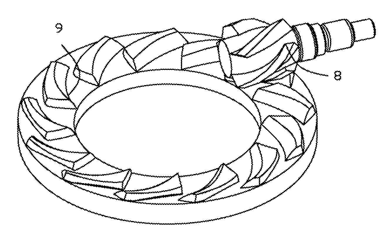
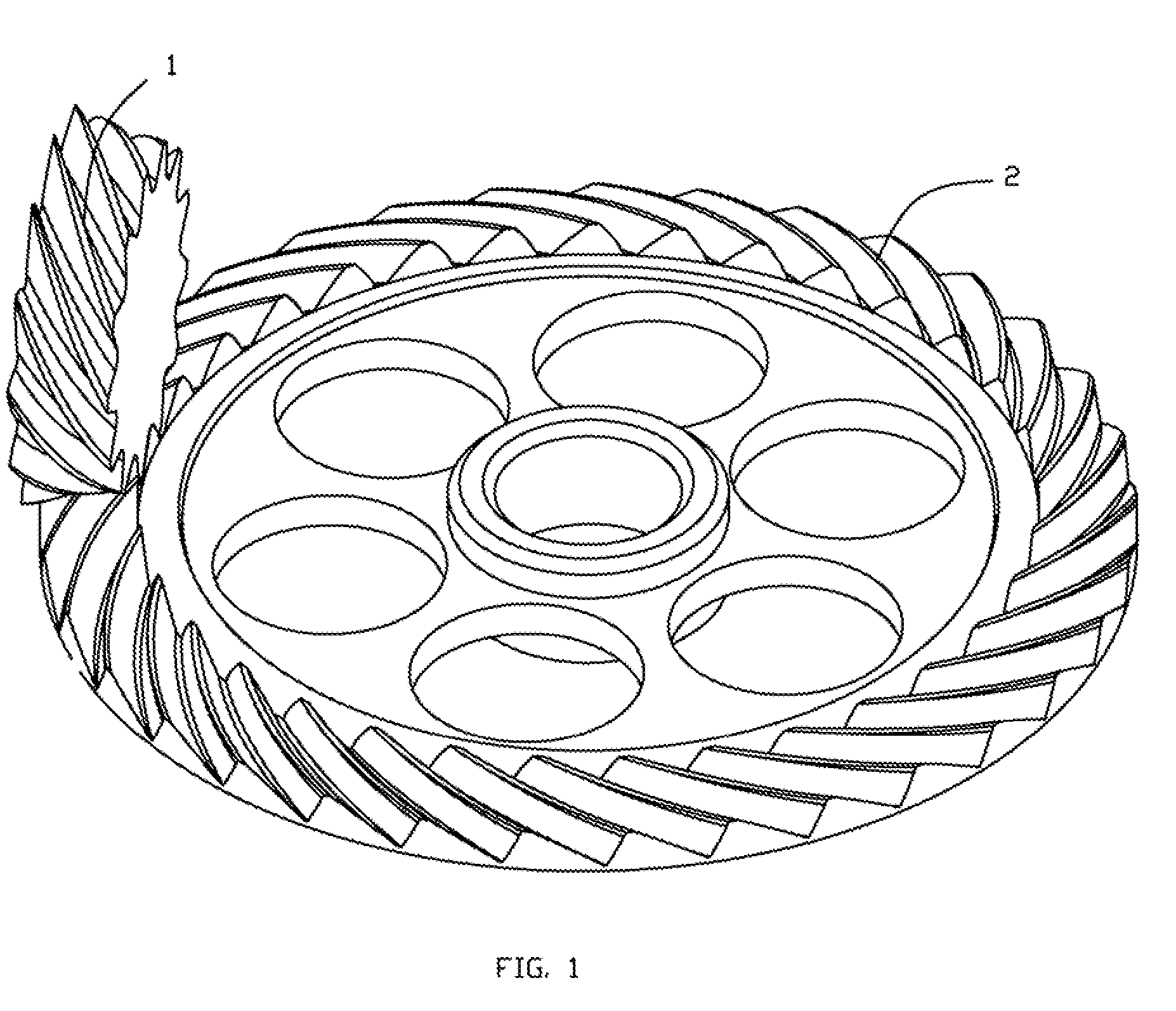
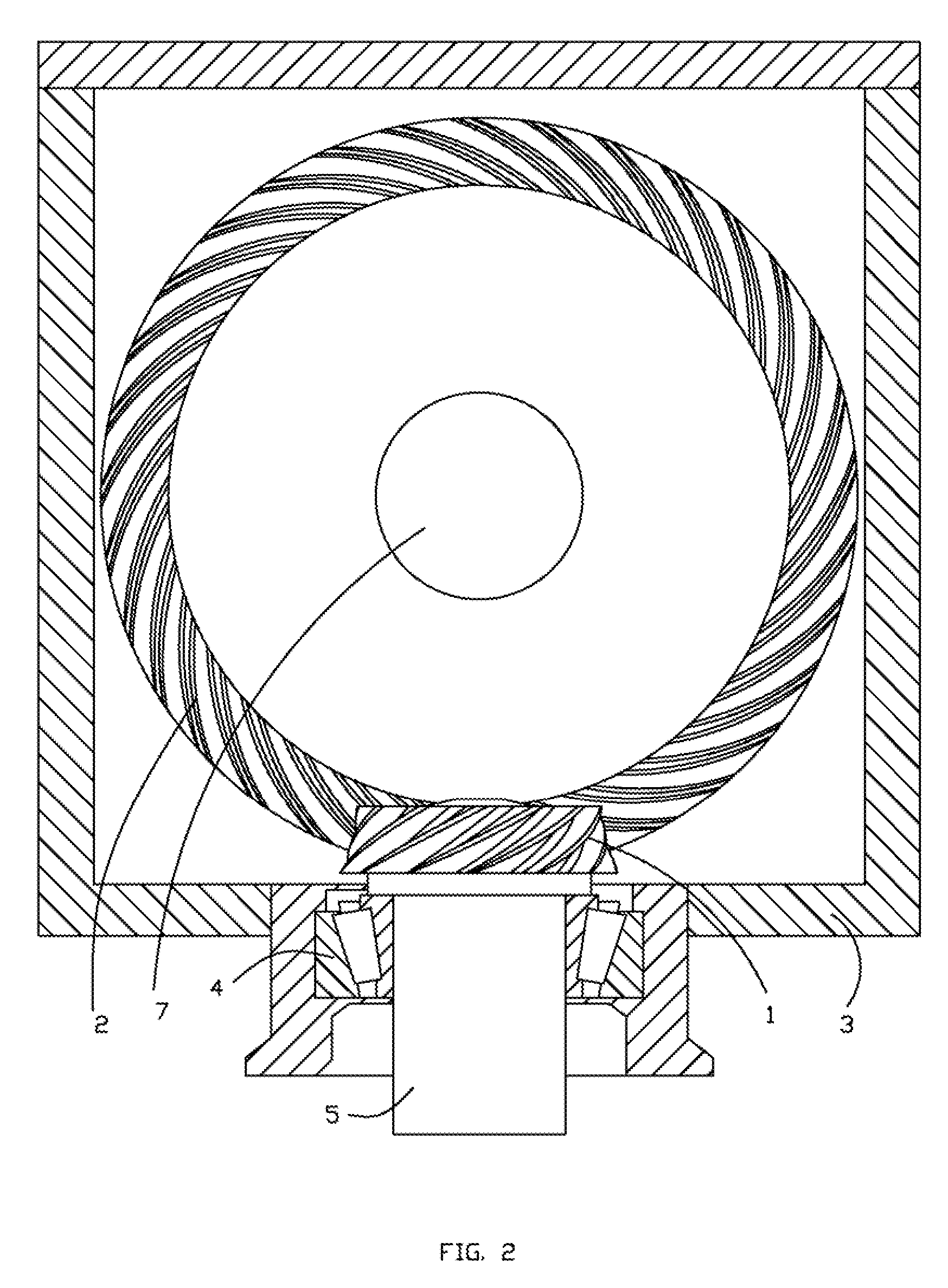
[0024] As will be detailed, an enveloping speed reducer with a unique worm-type input gearset embodying the principles of the present invention will be described below with reference to FIGS. 1 through 9. Initially, however, the following discussion provides a complete description of the enveloping worm face gear transmissions used for the worm-type-input gearset. Prior to specific consideration of the drawings, several unique features of the present invention can be discussed. In particular, the present invention is directed to gearsets having an enveloping worm face gear, where an enveloping worm is placed in mesh with a face gear. This type of gear produces contact pattern along the gear tooth line: from the left to the right or from the right to the left depending on the direction of rotation. This motion of contact pattern is very different from motion of contact pattern of any gears, used in drive axle assemble. For example in hypoid or spiral bevel gears contact pattern in mo...


PUM


Abstract

A speed reducer is provided with housing having support for a shaft of an enveloping worm and a shaft of a face gear. The enveloping worm placed into meshing engagement with the face gear. They have crossing or intersected axes. The enveloping worm face gears are used for mechanical power transition while reducing the noise and the weight of the speed reducer. It can replace worm, double helical, spiral bevel or hypoid gears

Description

[0001] This is a continuation-in-part of Ser. No. 10 / 854,363 filed May 27, 2004. [0002] The present invention relates generally to gears reducers, and more particularly, to gears box having an enveloping or globoid worm in mesh with a mating gear. This type of speed reducer could be used in medical devices industrial, automotive applications, and any mechanical power reduction systems.BACKGROUND OF THE INVENTION Field of the Invention [0003] Enveloping worm speed reducers, particular double enveloping worm gear drive are used in various applications as a high ratio, more than 5:1 of mechanical drive. In double enveloping speed reducer a pinion shaft and mating worm gear shafts are crossed. (U.S. Pat. No. 1,980,237 by Trbojevich, U.S. Pat. No. 5,836,076 by Duta and Prom: U.S. Pat. No. 5,018,403 by Umezono and Maki). Conventional enveloping worm / worm gear transmissions are using worm thread with at least one revolution of the thread or more than 360 degrees of revolution. [0004] Usual...

Claims


Application Information

Patent Timeline
Patent Type & Authority Applications(United States)
IPC IPC(8): F16H1/16F16H55/02F16H1/08F16H1/14
CPCF16H1/08F16H1/14Y10T74/19949Y10T74/19842F16H1/145
Inventor FLEYTMAN, YAKOV
Owner FLEYTMAN YAKOV
Features
  • Generate Ideas
  • Intellectual Property
  • Life Sciences
  • Materials
  • Tech Scout
  • Unparalleled Data Quality
  • Higher Quality Content
  • 60% Fewer Hallucinations
Learn More