Runflat device for a motor vehicle, and a mounted assembly incorporating it

Inactive Publication Date: 2006-01-12
HUTCHINSON SA
View PDF10 Cites 14 Cited by
  • Summary
  • Abstract
  • Description
  • Claims
  • Application Information

AI Technical Summary

Benefits of technology

[0043] It should be noted that using aluminum, titanium, or a composite for said rim c

Problems solved by technology

A major disadvantage of that runflat device is that its weight is relatively high, which makes mounted assemblies incorporating it heavier and thus renders v

Method used


Image

  • Runflat device for a motor vehicle, and a mounted assembly incorporating it
  • Runflat device for a motor vehicle, and a mounted assembly incorporating it
  • Runflat device for a motor vehicle, and a mounted assembly incorporating it

Examples


first embodiment

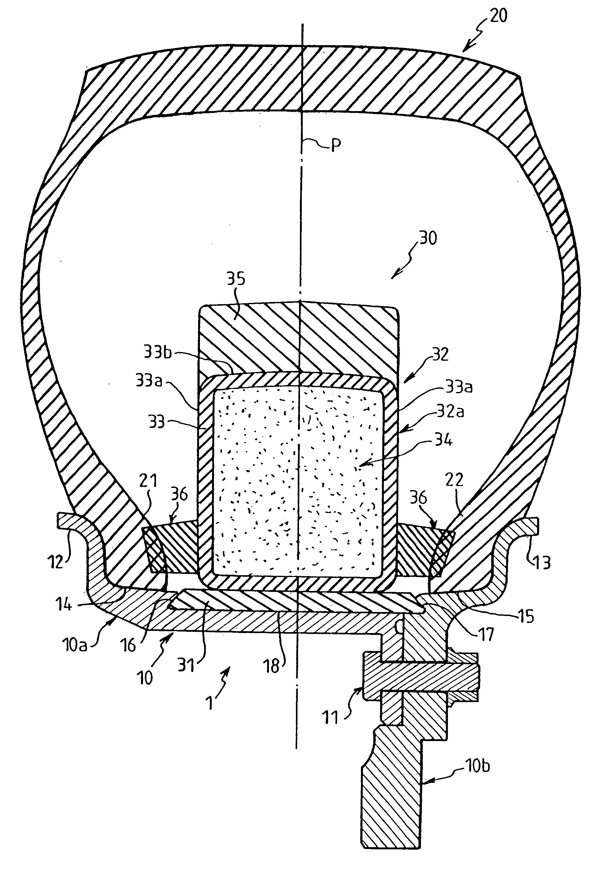
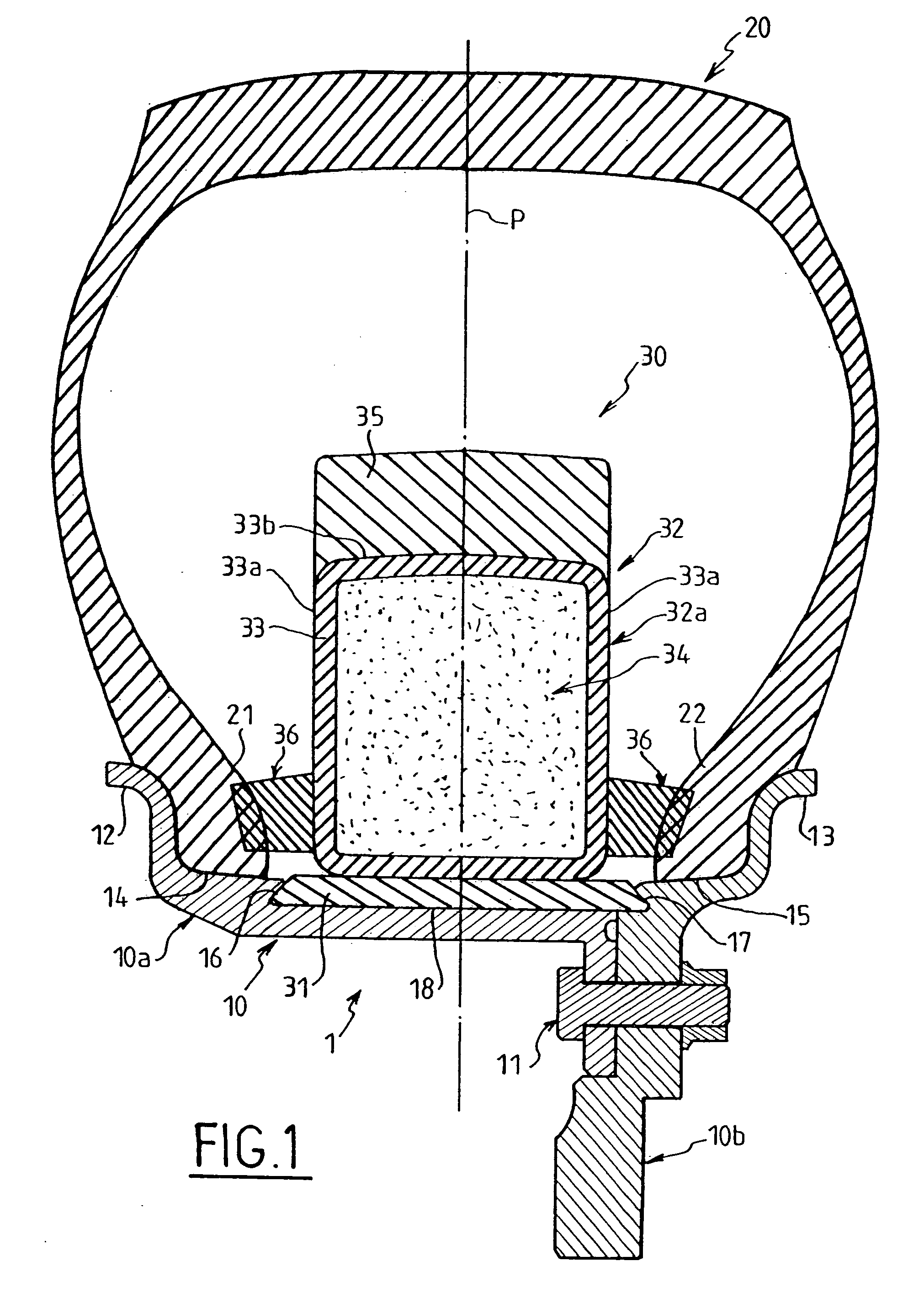
[0052] The mounted assembly 1 of the invention, shown in FIGS. 1 and 2, comprises a wheel rim 10 in two pieces 10a and 10b fixed to each other by bolt type fastener means 11.

[0053] The two blocks 10a and 10b respectively comprise axially inner and outer flanges 12 and 13 respectively defining two rim seats 14 and 15 extending axially from flanges 12 and 13, a tire cover 20, the beads 21 and 22 of which are supported on seats 14 and 15 and against flanges 12 and 13, and a runflat device 30 mounted around the rim 10 inside the tire cover 20 and designed to support it following a drop in inflation pressure inside the assembly 1.

[0054] The rim seats 14 and 15 extend radially inwardly via axially inner and outer lateral walls 16 and 17 connected by a base 18 and defining a circumferential rim recess 19 adapted to receive in abutment a radially inner portion of the device constituted by an annular sole 31.

[0055] To this end, the lateral walls 16 and 17 of recess 19 form undercuts which ...

second embodiment

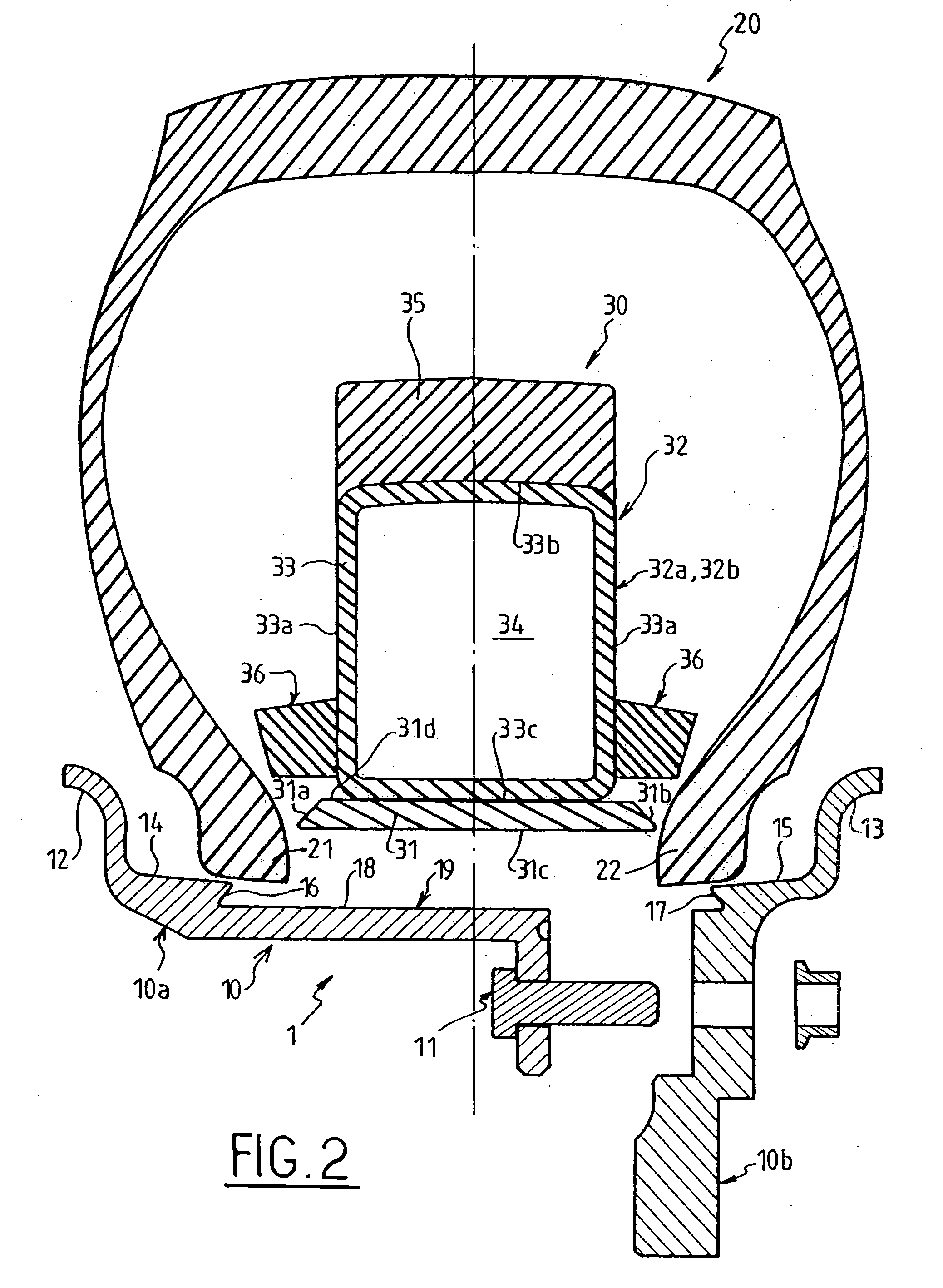
[0071] The mounted assembly 201 of the invention is illustrated in FIG. 6 and also comprises: [0072] a wheel rim 210 comprising two pieces 210a and 210b attached together using bolt type fastener means 211, pieces 210a, 210b respectively comprising axially inner and outer flanges 212, 213 respectively defining two rim seats 214, 215 extending axially from flanges 212, 213; [0073] a tire cover 220, the beads 221, 222 of which are supported on seats 214, 215 against the flanges 212, 213; and [0074] a runflat device 230 mounted around the rim 210 inside the tire cover 220 and designed to support it following a drop in inflation pressure inside the assembly 201.

[0075] In contrast to the first embodiment defined above, the rim 210 does not have a circumferential recess designed to receive a sole, but has a rim base 216 which is substantially flat provided with a circumferential groove 217 adjacent to the outer rim flange 213. The groove 217 is designed to receive an anchoring tab 231 of...

third embodiment

[0083] The mounted assembly 301 in the third embodiment shown in FIG. 7 differs from the assemblies 101, 201 described above in the following points:

[0084] Firstly, the rim 310 has a substantially flat rim base.

[0085] Secondly, each ring sector 332a, 332b has a radially inner zone 333a with an axial section in the form of an isosceles trapezoid the non parallel sides of which are directed radially outwardly towards each other to constitute two lateral application zones for two annular wedges 336 for locking beads 321, 322. Radially outwardly from said inner zone 333a, each ring sector has a radially outer zone 333b with a rectangular axial section (i.e. constant width).

[0086] Further, each wedge 336 is constituted by a one-piece rubber-based strip which has a “trapezoidal belt” shape adapted for being pressed during assembly (i.e. not bonded) by one of its non parallel sides against one side of said radially inner zone 333a. Each wedge 336 is advantageously strengthened with texti...


PUM


Abstract

The present invention concerns a runflat device for a tubeless mounted assembly for a motor vehicle and an assembly incorporating said device. A device in accordance with the invention for a unit comprises a wheel rim having a plurality of pieces and a tire cover comprising beads mounted against the flanges of the rim, the device comprising: a support ring for mounting around the rim to support the tire cover following a drop in inflation pressure and divided into at least two ring sectors; and means for locking said beads against the flanges to connect the sectors to the beads. The device is such that each ring sector comprises a rigid wall which defines at least one internal volume and which defines the lateral faces of the ring sector.

Description

[0001] The present invention relates to a runflat device for a tubeless mounted assembly for a motor vehicle, and to an assembly incorporating said device, allowing a large distance to be covered at a relatively high speed when the assembly is partially or completely deflated. Said runflat device is especially for use in a military vehicle designed for use on all types of terrain, including sand. BACKGROUND OF THE INVENTION [0002] Known runflat devices are generally constituted by a support ring which is mounted with some clearance about a wheel rim inside a tire cover. Said ring, constituted by a flexible material, is in a single piece and because of its width at its base, it exerts a force to flatten the tire on the rim. Occasionally, rigid devices in a plurality of pieces or sectors are fixed one to another. [0003] Japanese patent document JP-A-03 231007 discloses a runflat device for mounting around a wheel rim of the multi-piece type, comprising: [0004] a metal ring divided int...

Claims


Application Information

Patent Timeline
IPC IPC(8): B60C17/04B60B25/00B60B21/00B60C15/028
CPCB60C15/028B60C17/04B60C17/06Y10T152/10036Y10T152/10009Y10T152/10054B60C17/065
Inventor RESARE, LARS JOHANMARSALY, OLIVIERHEUZE, OLIVIER
Owner HUTCHINSON SA
Why Eureka
Try Eureka