Self-running robot

a self-running robot and robot technology, applied in the direction of conveyor counting, process and machine control, instruments, etc., can solve the problems of high manufacturing cost, inability to provide easy tracking and sensing of human movement, etc., and achieve the effect of simple arrangemen

Inactive Publication Date: 2006-01-12
FUNAI ELECTRIC CO LTD
View PDF4 Cites 36 Cited by
  • Summary
  • Abstract
  • Description
  • Claims
  • Application Information

AI Technical Summary

Benefits of technology

[0012] The present invention attempts to solve the above problems. An object of the present invention, therefore, is to provide a self-running robot capable of tracking and imaging a human body with a simple arrangement.

Problems solved by technology

Unfortunately, the inventions disclosed in Japanese Patent Laying-Open Nos. 06-098844 and 11-282533 do not provide easy tracking and sensing of the movement of a human body, since pyroelectric sensors are incapable of locating a human within the sensed areas.
The invention disclosed in Japanese Patent Laying-Open No. 2002-350555 requires higher manufacturing cost than is acceptable for a device merely for tracking and imaging a human body, since it fails to deal with noise generated during tracking and imaging of a human body.

Method used


Image

  • Self-running robot
  • Self-running robot
  • Self-running robot

Examples


first embodiment

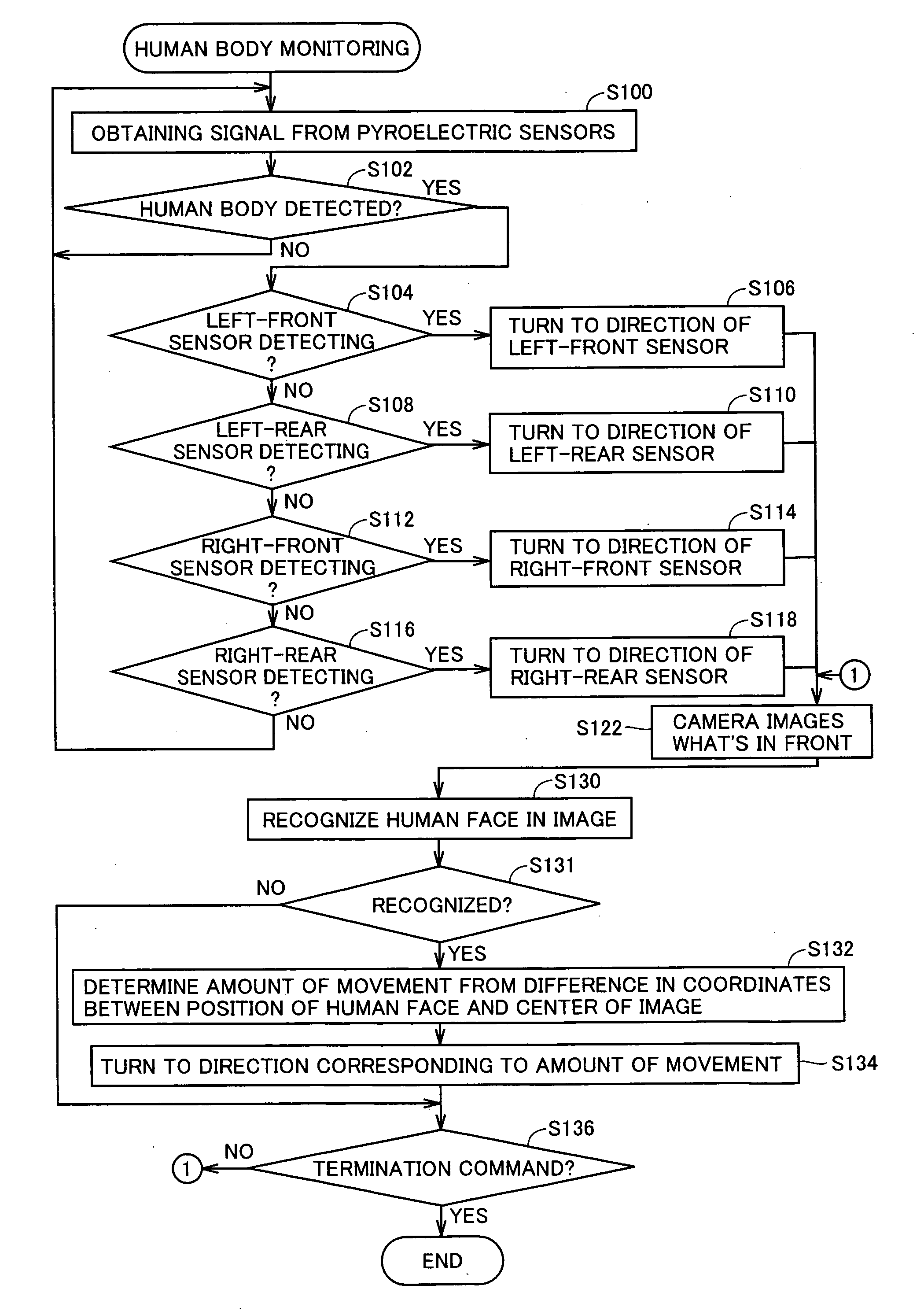
[0030] A self-running robot according to a first embodiment of the present invention is described below.

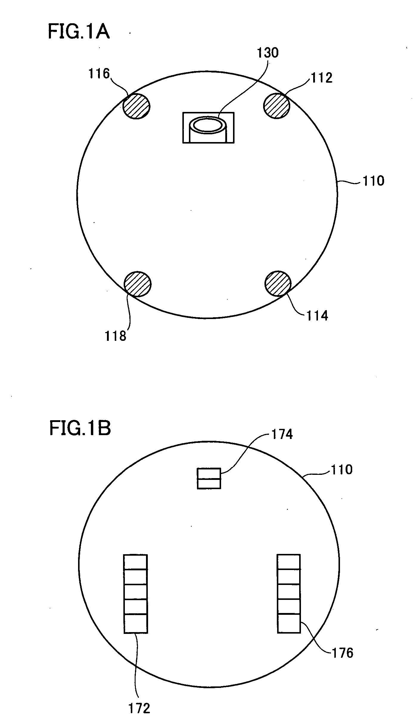
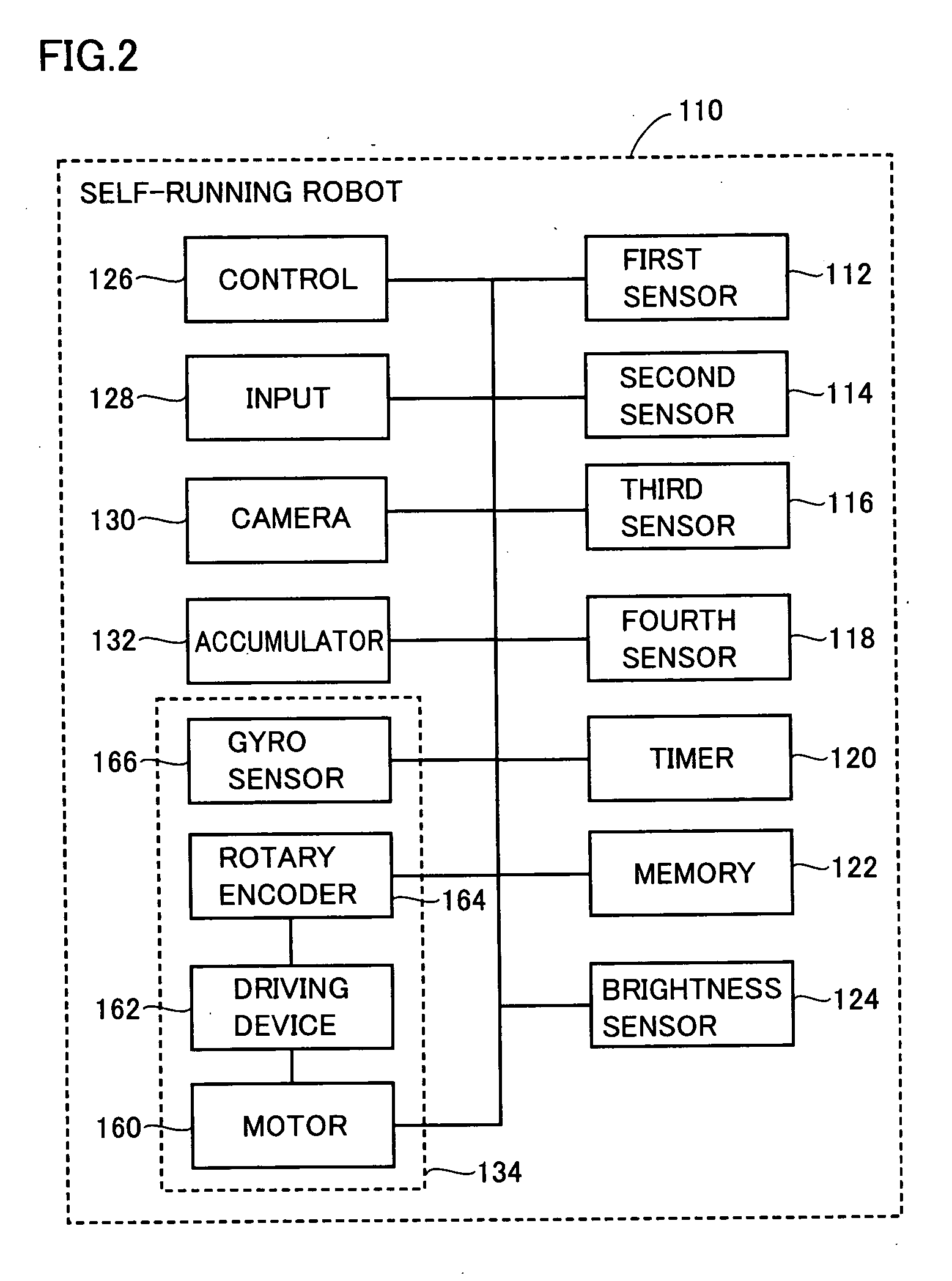
[0031] Referring to FIGS. 1A, 1B and 2, a self-running robot 110 according to the present embodiment includes a first sensor 112, a second sensor 114, a third sensor 116, a fourth sensor 118, a timer 120, a memory 122, a control unit 126, an input mechanism 128, a camera 130, an accumulator 132, and a running mechanism 134. FIGS. 1A and 1B show the external appearance of self-running robot 110 according to the present embodiment. Self-running robot 110 may be a disk-shaped robot that tracks and images an intruder in a user's home when the user is absent. FIG. 1A is a plan view and FIG. 1B is a bottom view of self-running robot 110. FIG. 2 is a control block diagram of self-running robot 110.

[0032] First to fourth sensors 112-118 may be pyroelectric sensors detecting the presence of a heat source (typically a human body) and outputting a signal. First sensor 112 is provided on th...

second embodiment

[0052] A self-running robot according to a second embodiment of the present invention will be described below.

[0053] Self-running robot 110 according to the present embodiment has the same hardware configuration as the first embodiment described above and has the same functions as well. Accordingly, a detailed description thereof will not be repeated.

[0054] Referring to FIG. 4, a program executed on self-running robot 110 according to the present embodiment performs the following operations for imaging an intruder. Note that in the flowchart shown in FIG. 4, those operations that have been discussed above referring to FIG. 3 are labeled with the same step numbers and are the identical operations. Accordingly, a detailed description thereof will not be repeated.

[0055] At S130, control unit 126 recognizes a human face in the image taken by camera 130. In the present embodiment, those of the pixels are extracted having a difference in tone from the surrounding pixels larger than a t...

third embodiment

[0068] A self-running robot according to a third embodiment of the present invention will be described below.

[0069] Referring to FIG. 5, a self-running robot 210 according to the present embodiment includes a first sensor 112, a second sensor 114, a third sensor 116, a fourth sensor 118, a timer 120, a memory 232, a control unit 126, an input mechanism 128, a complementary metal-oxide-semiconductor (CMOS) camera 240, an accumulator 132, and a running mechanism 134.

[0070] Memory 232 stores similar information to that stored in memory 122 of the first embodiment and, in addition, a data table indicating directions to which self-running robot 210 is to turn (hereinafter referred to as “data table”). The directions shown in FIG. 6 are those as viewed by a person opposite the front side of self-running robot 210. Referring to FIG. 6, the data table contains data indicating different combinations of detection and non-detection of a human body by the sensors and data indicating the direc...


PUM


Abstract

A self-running robot tracking and imaging a human body with an inexpensive arrangement includes: first to fourth sensors; a camera; a driving device moving the first to fourth sensors and camera simultaneously; a rotary encoder detecting that the first to fourth sensors and camera have stopped; a control unit which, upon detection of a heat source by one of the first to fourth sensors, controls the driving device such that the camera turns to the direction which the sensor detecting the heat source faced, and controls the camera so as to image an object after the camera has stopped, and controls the driving device such that the first to fourth sensors remain stationary for 3 seconds after the camera has stopped irrespective of whether a heat source is detected.

Description

BACKGROUND OF THE INVENTION [0001] 1. Field of the Invention [0002] The present invention relates to a self-running robot, and particularly, to a self-running robot used to provide security. [0003] 2. Description of the Background Art [0004] A conventional self-running robotic cleaner, such as that disclosed in Japanese Patent Laying-Open No. 06-098844 includes: a charge and power supply unit providing a direct voltage; a microprocessor that receives the direct voltage provided by the charge and power supply unit; a key input circuit that receives an action condition and an action command from a user to provide the action condition and the action command to the microprocessor; a thermal infrared radiation sensing circuit that senses thermal infrared radiation from a human body and a pet and provides a sense signal thereof to the microprocessor; a forward / backward movement motor driving circuit that receives a drive signal from the microprocessor to rotate a forward and backward moto...

Claims


Application Information

Patent Timeline
Patent Type & Authority Applications(United States)
IPC IPC(8): H01J40/14
CPCG05D1/0242G05D2201/0207G05D1/0272G05D1/0246
Inventor TAKENAKA, HIROYUKI
Owner FUNAI ELECTRIC CO LTD
Why Eureka
Try Eureka