Optical measurement system for living bodies and method thereof
a technology of optical measurement and living body, applied in the field of brain function measurement, can solve problems such as inability to provide satisfactory detecting capability, and achieve the effect of accurately assessing the response of a subject and satisfying detecting capability
- Summary
- Abstract
- Description
- Claims
- Application Information
AI Technical Summary
Benefits of technology
Problems solved by technology
Method used
Image
Examples
first embodiment
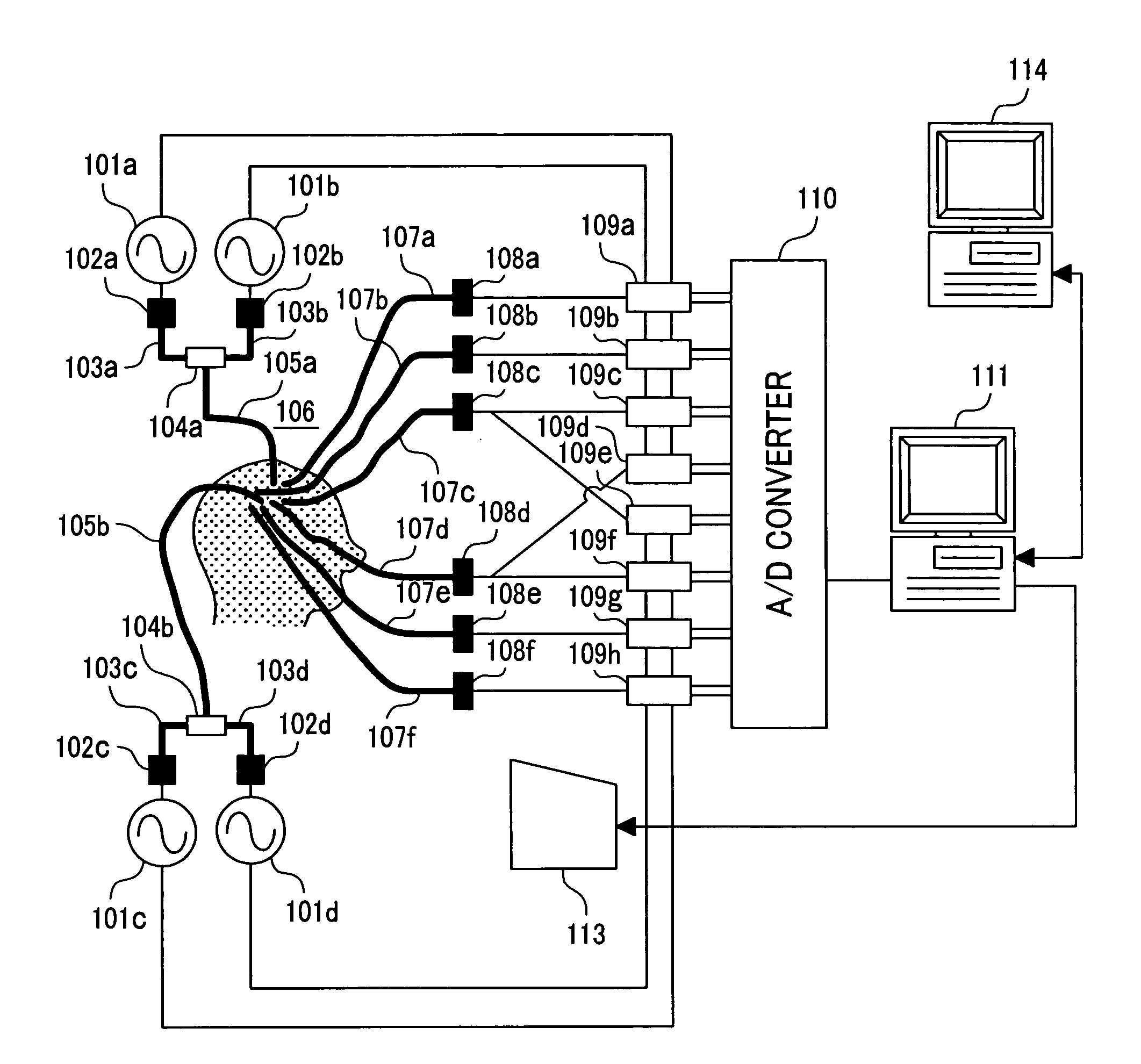
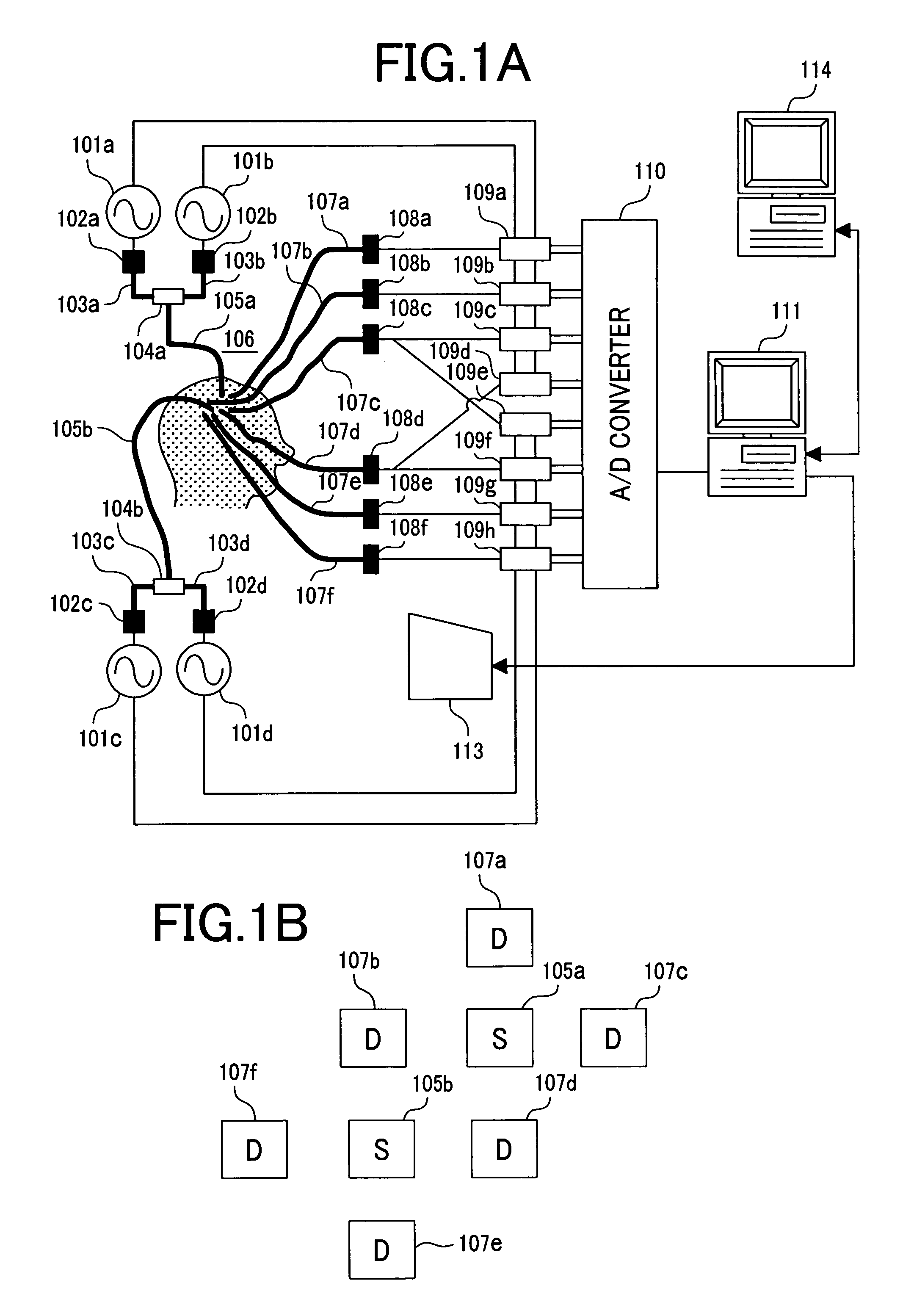
[0055]FIG. 3 is a block diagram showing the configuration of a living body measurement system in accordance with the first embodiment. The living body measurement system 210 corresponds to a measuring facility of the measurement control computer 111 shown in FIG. 1. The living body measurement system includes an interface 201 that provides the interface with the A / D converter 110, a CPU 202 that performs a series of actions, a storage unit 203 in which programs and data are stored, an interface 204 that provides the interface with external equipment 205, and a bus 206 over which these components are interconnected. Moreover, a display means 211, a keyboard 212, and a pointing device (for example, a mouse) 213 are connected on the bus, and used to present the results of analysis to an operator of the measurement control computer 111. Moreover, the operator uses the display means 211, keyboard 212, and pointing device to enter data. Herein, the programs stored in the storage unit 203 ...
second embodiment
[0063] The second embodiment is concerned with detection of an activity performed by asking an examinee to listen to the played-back commentary on a baseball game as a stimulus / task instruction sequence and to imagine standing on a field as a batter. FIG. 5A illustratively shows an example of the structures of probes employed in the second embodiment and the arrangement of the probes, and also shows the results of assessment of the synchronousness of the phase of a signal. An oval drawing expresses the head seen from above, and a triangle expresses the nose seen from above. Probes 1, 2, 3, and 4 are arranged on the frontal region of the head, the right and left temporal regions thereof, and the occipital region thereof. The probes 1, 2, and 3 are structured so that twenty-two measurement channels will be formed in each probe. The probe 4 is structured so that twenty-four measurement channels will be formed therein.
[0064]FIG. 5A illustratively shows an example of the structures of t...
third embodiment
[0067] According to the second embodiment, a subject's brain activity is detected by adopting a played-back signal, which is heard, as a standard signal. The levels of synchronousness of the phases of signals may be assessed, and a signal which is produced in a channel and whose phase is highly synchronous with the phase of the standard signal may be adopted as a new standard signal. In this case, an active brain area can be detected further exactly.
[0068] According to the third embodiment, first, a measurement channel in which a signal which is produced responsively to hearing of a played-back signal and whose phase is highly synchronous with the phase of the played-back signal serving as a standard signal is produced is detected. FIG. 6 shows detected measurement channels in which a signal which is produced responsively to hearing of the played-back signal and whose phase is highly synchronous with the phase of the standard signal is produced. In this example, a signal that is mo...
PUM
 Abstract
Description
Claims
Application Information
 - R&D
- Intellectual Property
- Life Sciences
- Materials
- Tech Scout
- Unparalleled Data Quality
- Higher Quality Content
- 60% Fewer Hallucinations
Browse by: Latest US Patents, China's latest patents, Technical Efficacy Thesaurus, Application Domain, Technology Topic, Popular Technical Reports.
© 2025 PatSnap. All rights reserved.Legal|Privacy policy|Modern Slavery Act Transparency Statement|Sitemap|About US| Contact US: help@patsnap.com


