
Connecting device

a technology of connecting device and accessory, which is applied in the direction of towing device, transportation and packaging, vehicle components, etc., can solve the problems of affecting the safety of connecting device,

Inactive Publication Date: 2006-01-12
IRON CONCEPTS
View PDF13 Cites 2 Cited by
  • Summary
  • Abstract
  • Description
  • Claims
  • Application Information

AI Technical Summary

Benefits of technology

[0014] In another of its aspects, the invention includes a collar for securing an accessory to a hitch receiver with an outward end defining an opening. The collar has an interior part configured to fit inside the opening, and an exterior part extending outside the outward end from the interior part when the collar is urged inwardly against the outward end for engaging the outward end. The exterior part prevents inward movement of the collar upon engagement thereof. The collar is adapted to be coupled with the accessory so that the accessory is secured to the hitch receiver upon the engagement of the collar to the outward end of the hitch receiver.

Problems solved by technology

Various devices for connecting an accessory to a hitch receiver are known, but such devices suffer from a number of imperfections or weaknesses.
For example, accessories connected to hitch receivers by known devices tend to wobble relative to the hitch receiver (and the vehicle) as the vehicle travels, even where the connection is relatively secure.
If not secured again to the hitch receiver after wobbling starts, the connecting device can gradually become less secure, even to the extent of disconnection.
In addition, wobbling movement of the accessory relative to the hitch receiver can lead to the bicycles or other cargo on the accessory being jarred loose, and falling off the accessory.
Also, known connecting devices do not provide for relatively fast and simple disconnection of the accessory from the hitch receiver.

Method used


Image

  • Connecting device
  • Connecting device
  • Connecting device

Examples


Embodiment Construction

)

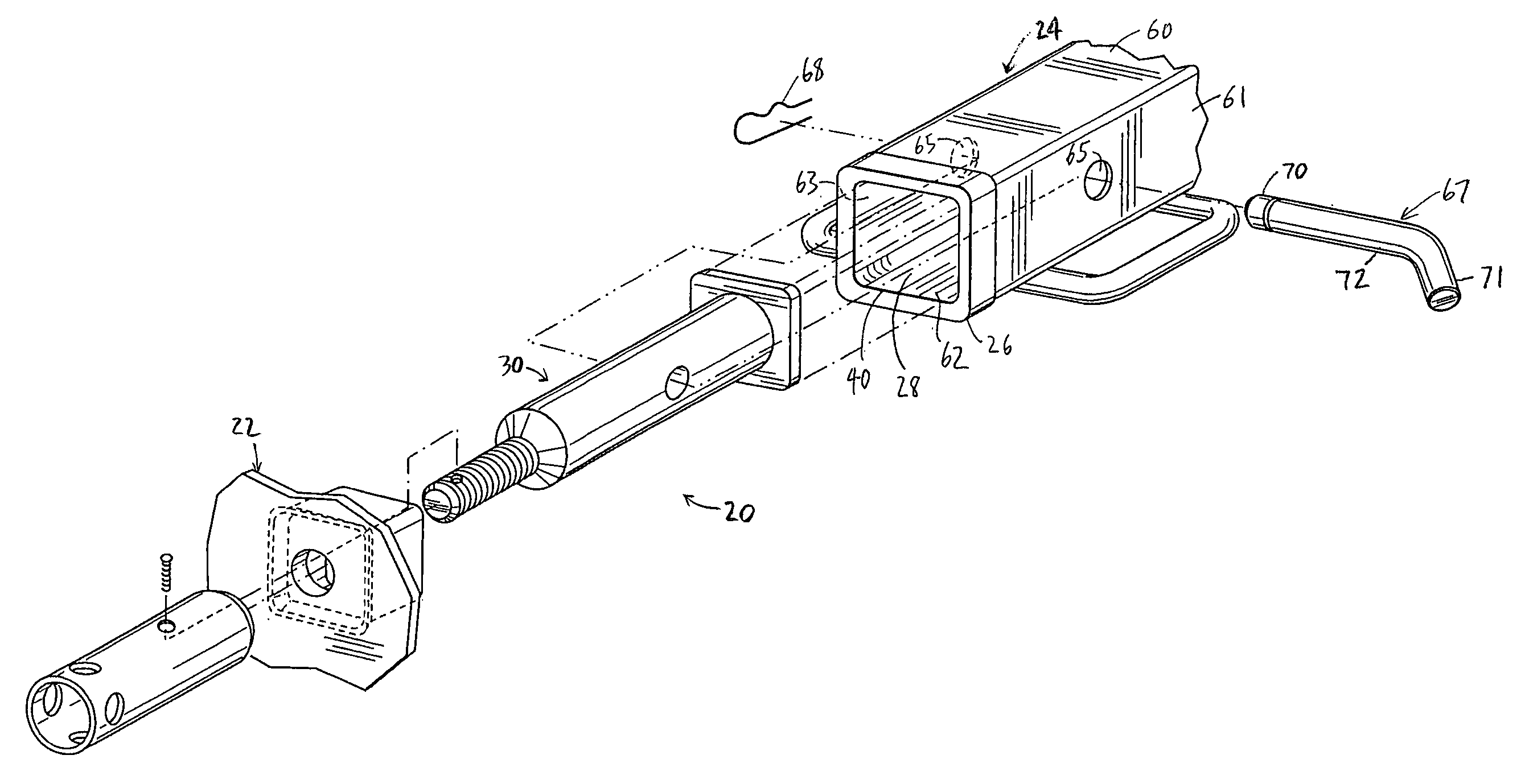
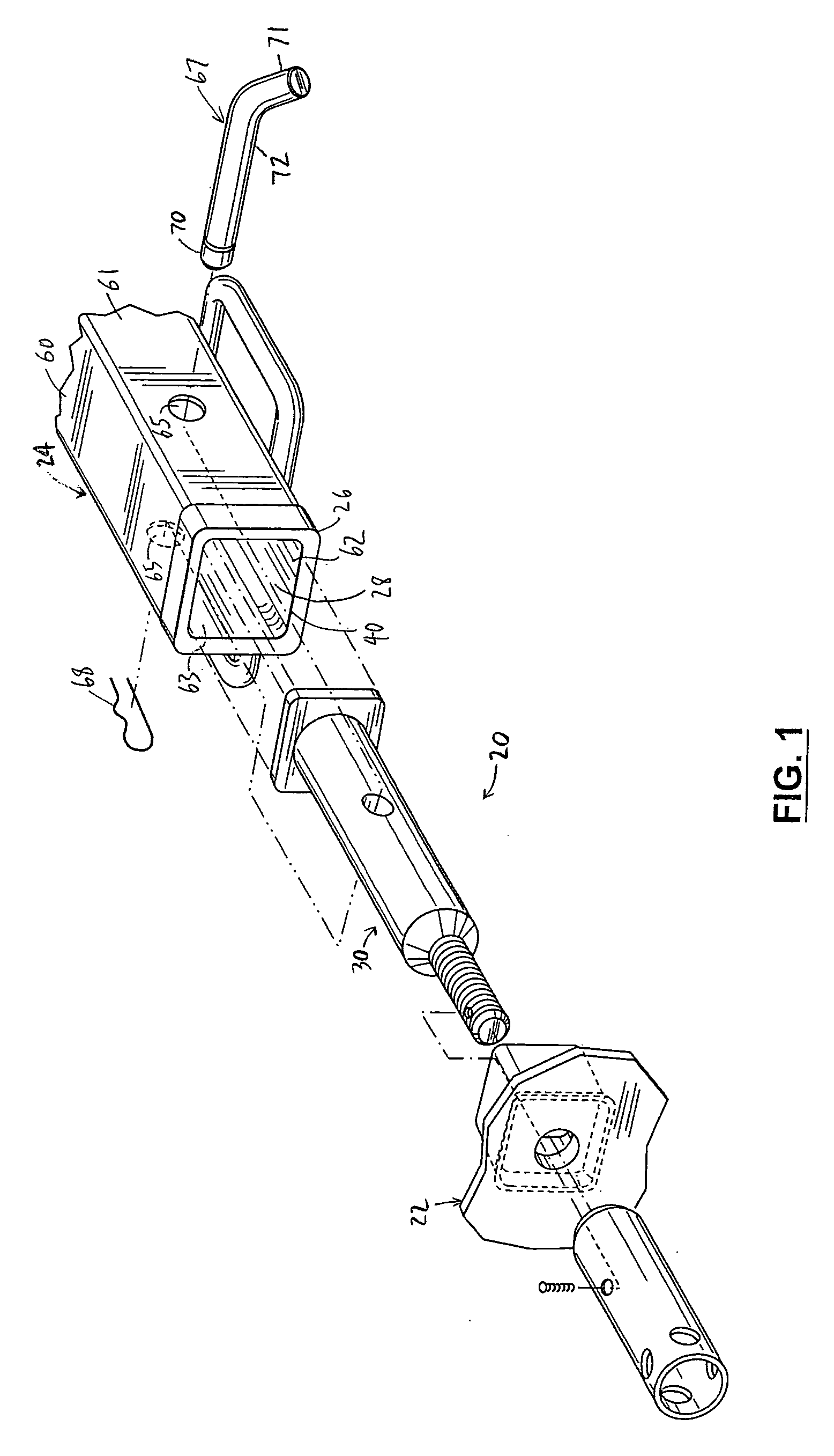
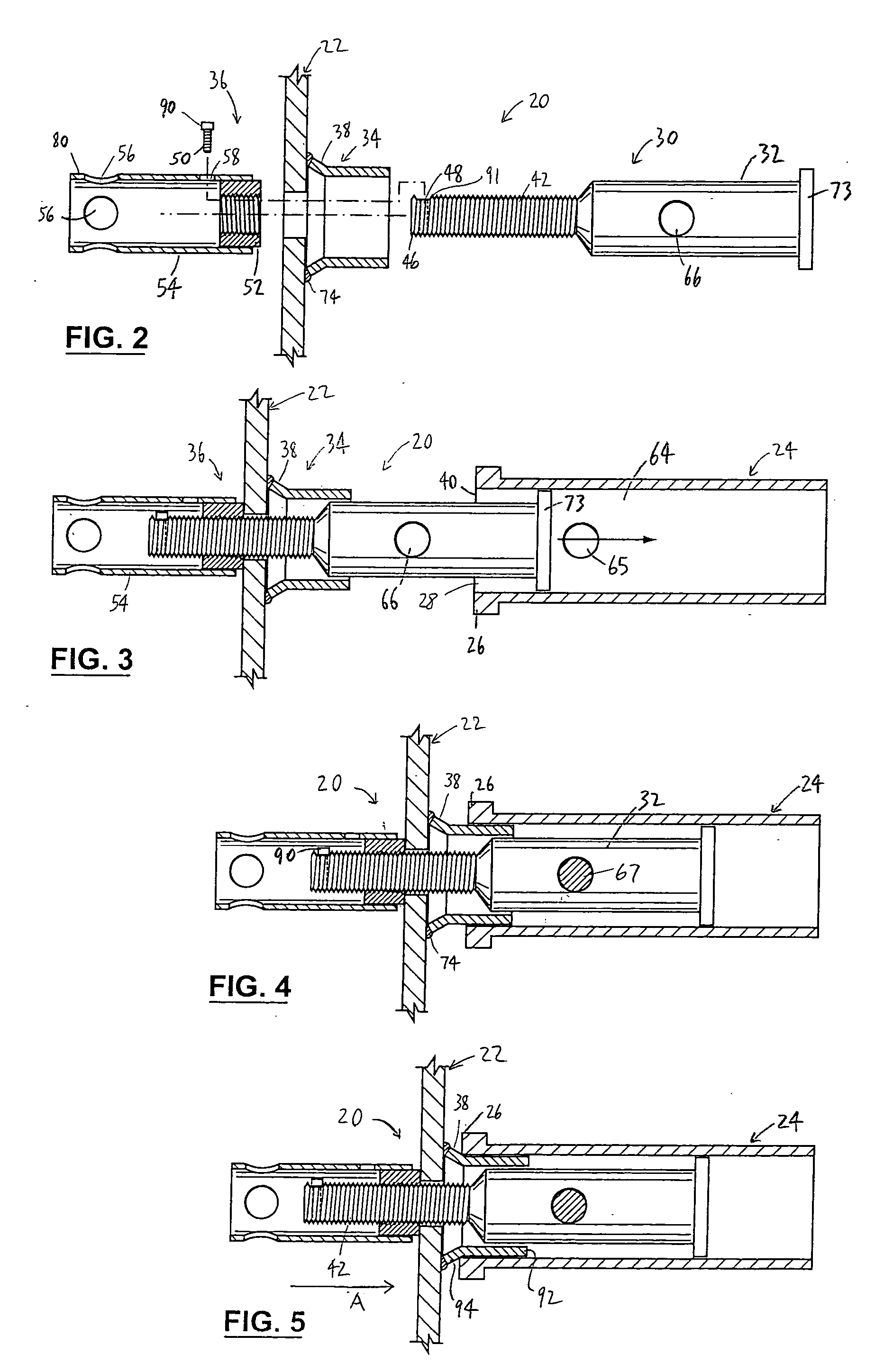
[0028] Reference is first made to FIGS. 1-6 to describe a preferred embodiment of a connecting device in accordance with the invention indicated generally by the numeral 20. The connecting device is for connecting an accessory 22 to a hitch receiver 24 which has an outward end 26 defining an opening 28. As shown in FIGS. 1, 3, 4, and 6, the connecting device 20 includes a base 30 with a body portion 32 receivable in the hitch receiver 24. The body portion 32 is adapted for coupling with the hitch receiver 24 to locate the base 30 in a predetermined position therein, as will be described. The connecting device 20 also includes a collar 34 for engaging the outward end 26 of the hitch receiver 24 in an interference fit upon engagement of the collar 34 with the outward end 26, as shown in FIGS. 5 and 6. The collar 34 is preferably coupled with the accessory 22. In addition, the connecting device includes a fastener 36 operatively connected with the base 30 and operable to urge the coll...


PUM


Abstract

A connecting device for connecting an accessory to a hitch receiver with an outward end defining an opening. The connecting device has a base with a body portion receivable in the hitch receiver. The body portion is adapted for coupling with the hitch receiver to locate the base in a predetermined position thereon. The connecting device also has a collar for engaging the outward end of the hitch receiver in an interference fit upon engagement of the collar with the outward end, the collar being coupled with the accessory. In addition, the connecting device includes a fastener operatively connected with the base for urging the collar against the outward end to cause the collar to engage the outward end. The connecting device connects the accessory to the hitch receiver upon engagement of the collar with the outward end of the hitch receiver.

Description

FIELD OF THE INVENTION [0001] This invention is related to a connecting device for connecting an accessory to a hitch receiver. BACKGROUND OF THE INVENTION [0002] Hitch receivers are commonly used for attaching accessories to vehicles. The accessories are bicycle racks, cargo baskets, or various carriers and the like, and they are usually attached to a vehicle at its back end. Typically, a hitch receiver is a tube which is substantially square in cross-section (often with rounded corners) and attached to the vehicle beneath a rear bumper. The accessory is typically intended to support and hold one or more bicycles, cargo, or other similar articles. [0003] The typical hitch receiver is ideal for supporting the typical accessory because the hitch receiver is located at the back end of the vehicle and is securely attached to the vehicle. For example, the hitch receiver is commonly welded or otherwise secured to a chassis or frame of the vehicle. [0004] Various devices for connecting an...

Claims


Application Information

Patent Timeline
Patent Type & Authority Applications(United States)
IPC IPC(8): B60D1/00
CPCB60D1/52B60D1/155
Inventor SHOEMAKER, CRAIG
Owner IRON CONCEPTS
Learn More