Regulator valve for a torque-transmitting mechanism and method of engaging a torque-transmitting mechanism

Active Publication Date: 2006-01-12
GM GLOBAL TECH OPERATIONS LLC
View PDF8 Cites 6 Cited by
  • Summary
  • Abstract
  • Description
  • Claims
  • Application Information

AI Technical Summary

Benefits of technology

[0011] In yet another aspect of the invention, the method includes biasing the spool valve in an opposing direction, preferably via a spring. The method may further include decreasing oil pressure on the first pressure responsive area and sliding the valve in the opposing directi

Problems solved by technology

This results from increasing p

Method used


Image

  • Regulator valve for a torque-transmitting mechanism and method of engaging a torque-transmitting mechanism
  • Regulator valve for a torque-transmitting mechanism and method of engaging a torque-transmitting mechanism
  • Regulator valve for a torque-transmitting mechanism and method of engaging a torque-transmitting mechanism

Examples


Embodiment Construction

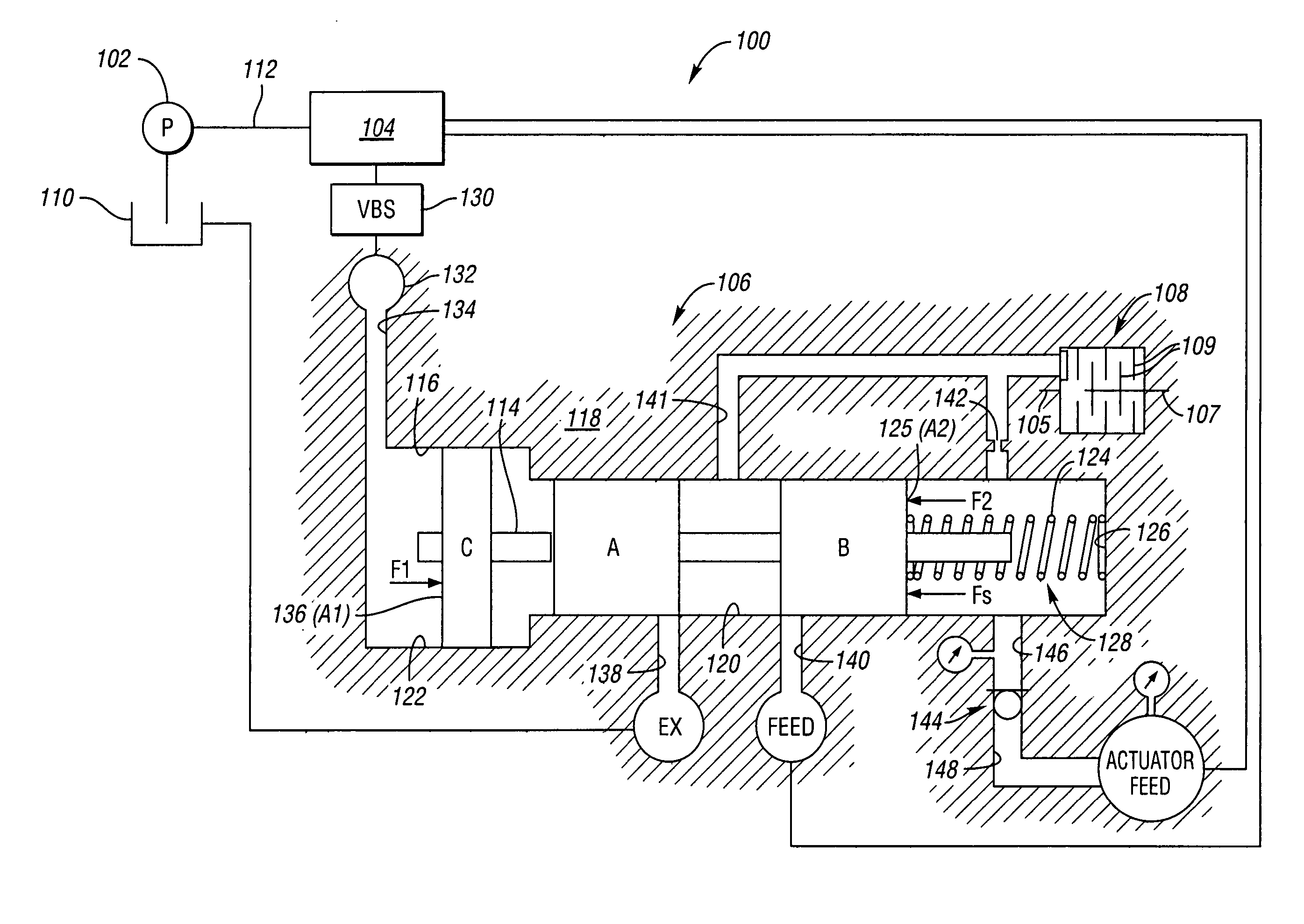
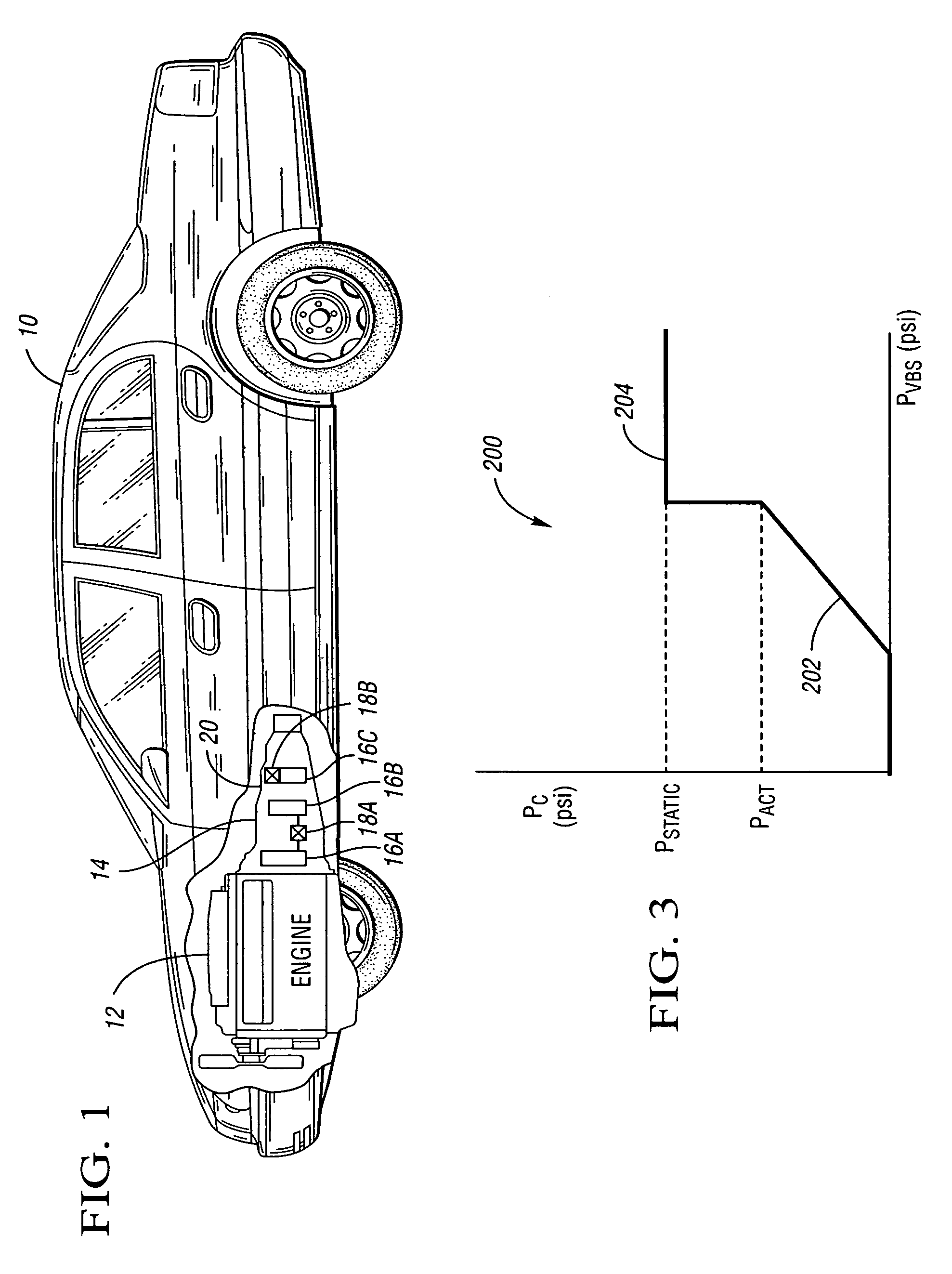
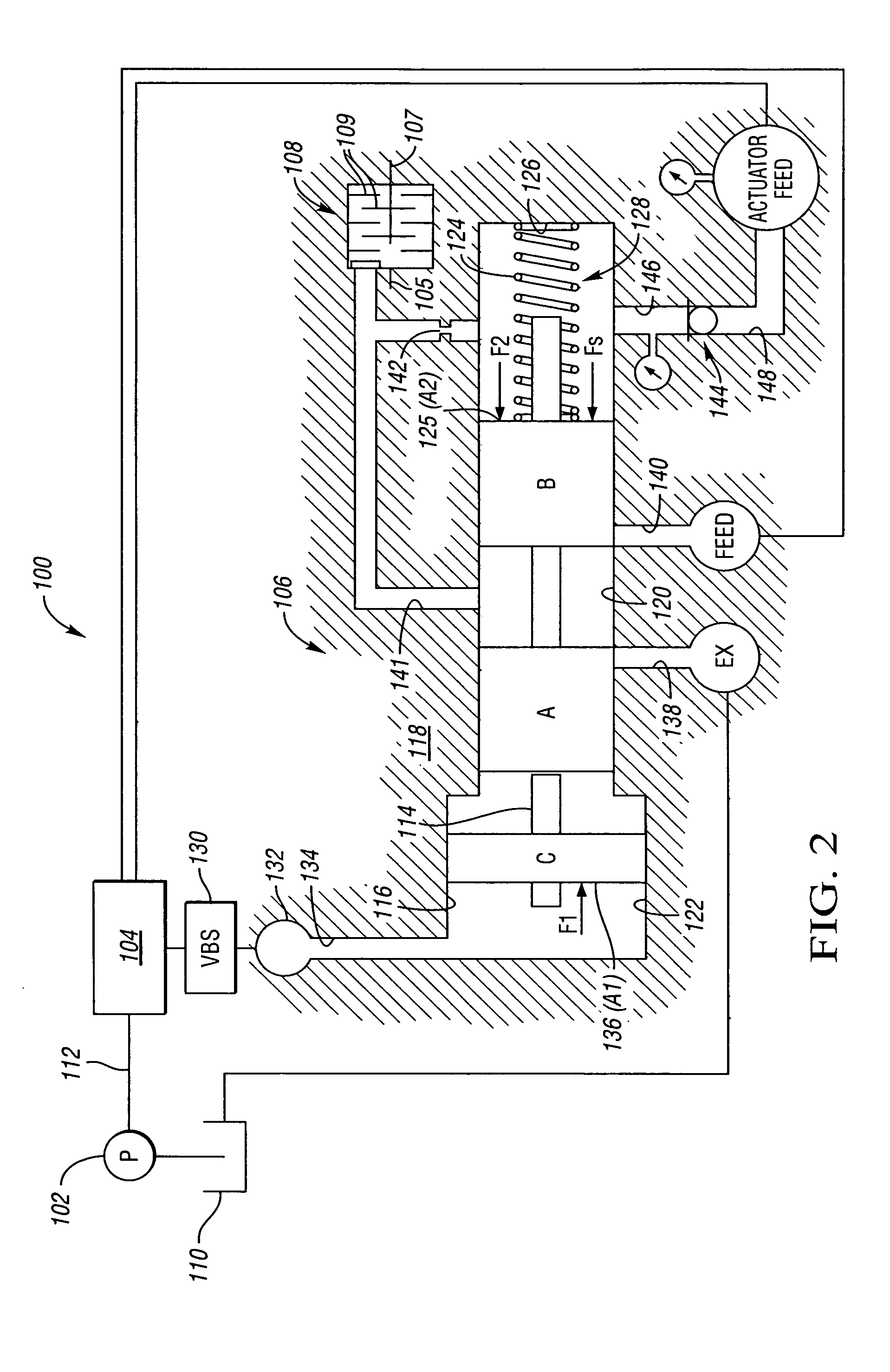
[0016] Referring to the drawings, wherein like reference numbers refer to like components, FIG. 1 shows a vehicle 10 having an engine 12 connected with a transmission 14. The transmission 14 includes three planetary gear sets 16A, 16B and 16C. Torque-transmitting mechanisms interconnect gear elements of the planetary gear sets to one another, such as rotating clutch 18A, or to a stationary transmission housing 20, such as brake 18B. FIG. 2 shows a portion of a transmission control system 100 including a pump 102, an electro-hydraulic control 104, a regulator valve 106 and a torque-transmitting mechanism 108, which, in this embodiment, is a clutch. The pump 102 draws hydraulic fluid (oil) from a reservoir 110 and delivers it to the electro-hydraulic control 104 through a main passage 112.

[0017] The electro-hydraulic control 104 includes an electronic control unit (ECU) having a conventional preprogrammed digital computer and also includes conventional control valves that distribute ...


PUM


Abstract

A regulator valve for controlling the pressure of fluid engaging a torque-transmitting mechanism in a transmission includes a valve body forming a valve bore of a plurality of passages. A spool valve slides within the valve body. A check valve selectively opens and closes one of the passages. A spring is disposed in the valve bore and biases the spool valve in one direction. The spool valve, check valve, spring, valve bore and passages are configured to control the pressure fluid provided to the torque-transmitting mechanism and a linearly increasing pressure until a first predetermined pressure is achieved and then at a second constant predetermined pressure greater than the first predetermined pressure, thus combining gradual clutch engagement during shifting with valve boost necessary for static capacity requirements. A method of controlling engagement of the torque-transmitting mechanism is also provided.

Description

CROSS-REFERENCE TO RELATED APPLICATIONS [0001] This application claims the benefit of U.S. Provisional Application No. 60 / 586,651, filed Jul. 9, 2004, which is hereby incorporated by reference in its entirety.TECHNICAL FIELD [0002] The invention relates to an oil flow arrangement for controlling fluid pressure to a torque-transmitting mechanism; specifically, a regulator valve for a torque-transmitting mechanism in a power transmission. BACKGROUND OF THE INVENTION [0003] Regulator valves responsive to a hydraulic pressure conveyed via an electro-hydraulic control unit are used to control pressure gain of a torque-transmitting mechanism during engagement of the torque-transmitting mechanism. It is desirable to provide a gradual clutch pressure increase during shifting for smooth engagement. Often, a jump or boost in pressure provided at the clutch is required after the period of gradual increase to meet higher static pressure requirements at full engagement. SUMMARY OF THE INVENTION ...

Claims


Application Information

Patent Timeline
IPC IPC(8): B60T13/00
CPCF16D48/02F16H2061/0253F16H61/065F16D2048/0209Y10T137/86614
Inventor BERGER, TODD R.MOORMAN, STEVEN P.WHITMARSH, BRIAN W.
Owner GM GLOBAL TECH OPERATIONS LLC
Why Eureka
Try Eureka