Programable logic device, configuration apparatus, and configuration method
- Summary
- Abstract
- Description
- Claims
- Application Information
AI Technical Summary
Benefits of technology
Problems solved by technology
Method used
Image

Examples
first embodiment
The First Embodiment
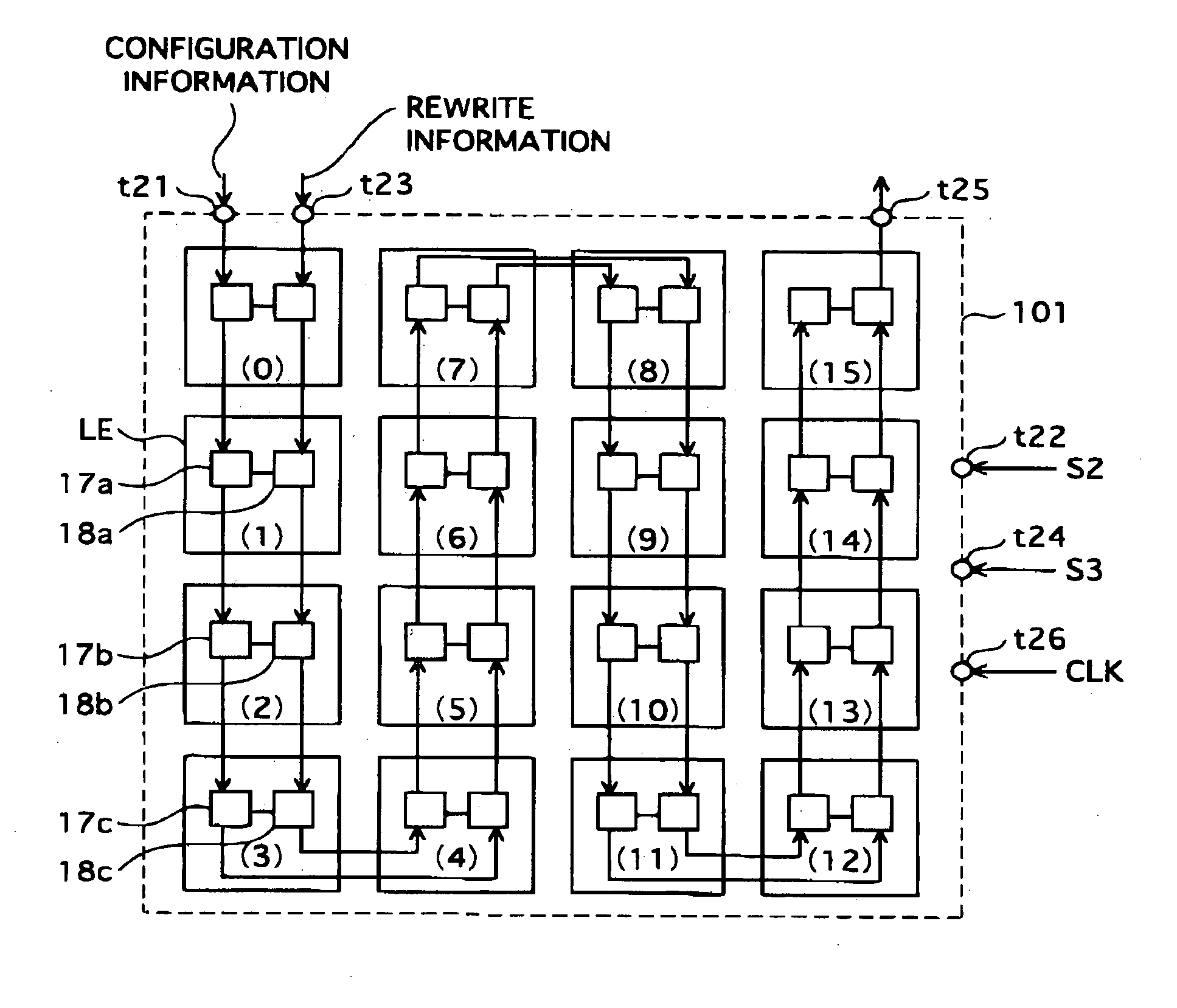
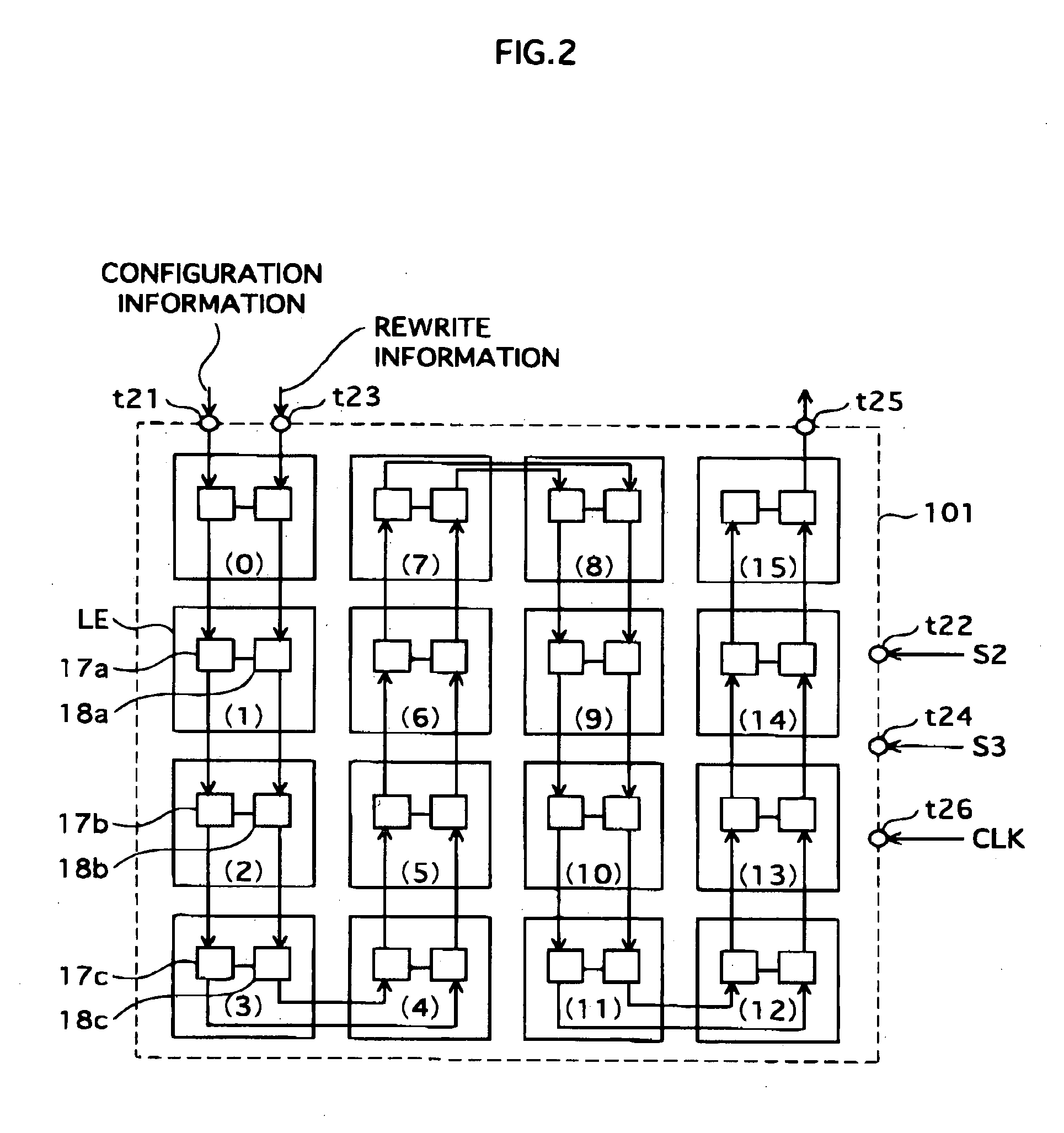
[0083]FIG. 2 shows a structure of a programmable logic device according to the first embodiment,
[0084] A programmable logic device 101 includes sixteen logic elements (LE0-LE15). Each logic element includes a unit cell 17 and a unit cell 18. Each unit cell 17 includes a configuration storing unit 11, and each unit cell 18 includes a rewrite information storing unit 14. The configuration storing unit 11 stores a piece of configuration information that defines a function of the logic element. The rewrite information storing unit 14 stores a piece of rewrite information that indicates whether the piece of the configuration information stored in the configuration storing unit 11 should be rewritten or not.
[0085] The configuration storing units are connected to each other by a cascade connection and structure a shift register. The rewrite information storing units are also connected to each other by a cascade connection and structure a shift register.
[0086] The fir...
second embodiment
The Second Embodiment
[0142]FIG. 14 shows the structure of a programmable logic device according to the second embodiment.
[0143] A programmable logic device 201 includes sixteen logic elements (LE). Each logic element includes a unit cell 26 and a unit cell 27. Each unit cell 26 includes a first storing unit 21, and each unit cell 27 includes a second storing unit 23. Each of the first storing unit 21 and the second storing unit 23 stores a piece of configuration information that defines a function of the logic element.
[0144] The first storing units respectively included in the logic elements are connected to each other by a cascade connection and structure a shift register. Being independent of this shift register, the second storing units respectively included in the logic elements are also connected to each other by a cascade connection and structure another shift register.
[0145] The second embodiment is characterized by that the function of the logic element is defined in adva...
third embodiment
The Third Embodiment
[0173]FIG. 17 shows the structure of a programmable logic device according to the third embodiment.
[0174] The programmable logic device 301 includes sixteen logic elements (LE). Each logic element includes a unit cell 35 and a unit cell 36. Each unit cell 35 includes a preparatory storing unit 31, and each unit cell 36 includes a main storing unit 33. Each of the preparatory storing unit 31 and the main storing unit 33 stores a piece of configuration information that defines a function of the logic element.
[0175] The preparatory storing units respectively included in the logic elements are connected to each other by a cascade connection and structure a shift register.
[0176] Each main storing unit 33 stores a piece of the configuration information stored in the preparatory storing unit 31 in accordance with a rewrite instruction.
[0177] The third embodiment is characterized by that the main storing unit 33 intervenes between the preparatory storing unit 31 that...
PUM
 Abstract
Description
Claims
Application Information
 - R&D Engineer
- R&D Manager
- IP Professional
- Industry Leading Data Capabilities
- Powerful AI technology
- Patent DNA Extraction
Browse by: Latest US Patents, China's latest patents, Technical Efficacy Thesaurus, Application Domain, Technology Topic.
© 2024 PatSnap. All rights reserved.Legal|Privacy policy|Modern Slavery Act Transparency Statement|Sitemap