Image processing apparatus and its method

a technology of image processing and image information, applied in the field of color management, can solve the problems of inability to adjust the default icc profile of devices, and inability to handle the color information of display devices as that of output devices, etc., and achieve the effect of easy adjustment of profiles

Inactive Publication Date: 2006-01-12
CANON KK
View PDF21 Cites 24 Cited by
  • Summary
  • Abstract
  • Description
  • Claims
  • Application Information

AI Technical Summary

Benefits of technology

[0011] According to the present invention, profiles can be easily adjusted. Also, profiles can be adjusted using a relatively small number of patches.

Problems solved by technology

Since display devices such as monitors and the like have different color gamuts from output devices such as printers and the like, color information of display devices cannot be handled as that of output devices intact.
However, every devices inevitably suffer characteristic variations due to aging, and default ICC profiles are not always optimal to devices whose characteristics have varied.
Also, even when identical profiles are used in identical devices, images with the same tint are not always obtained depending on individual differences of the devices.
A state wherein a plurality of devices have different tints especially poses a problem in a cluster printer environment in which identical images are distributed to and output by a plurality of printers.
Hence, profile re-generation requires a long time.
Furthermore, when a series of operations, i.e., print, colorimetry, and calculations are made in correspondence with a plurality of devices, a longer time is required.
For this reason, it is difficult for devices whose device characteristics readily vary day by day such as electrophotographic color printers and the like to routinely re-generate profiles.

Method used


Image

  • Image processing apparatus and its method
  • Image processing apparatus and its method
  • Image processing apparatus and its method

Examples


first embodiment

[Arrangement]

[0031]FIG. 3 is a block diagram showing the arrangement of an image processing system according to the first embodiment.

[0032] Multi-functional peripheral equipments (MFPs) 101 and 102, management PC 104, client PCs 105 and 106, and the like are connected to a network 108 in an office 10. In this environment, the users of the client PCs 105 and 106 issue print instructions as needed using various applications. Upon issuance of the print instruction, a printer driver installed in each of these PCs generates page description language (PDL) data described in a PDL on the basis of data supplied from the application, and transmits the PDL data to the MFP designated by the user. Each of the MFPs 101 and 102 converts the PDL data sent via the network 108 into a format that can be processed by its printer engine, and supplies the converted data to the printer engine.

[0033] The management PC 104 executes a process of calorimetric values obtained by a calorimeter 103 connected...

second embodiment

[0092] The image processing according to the second embodiment of the present invention will be described below. Note that the same reference numerals in this embodiment denote the same components as those in the first embodiment, and a detailed description thereof will be omitted.

[0093] Another method of updating the Lab to CMYK LUT will be described below. FIG. 16 is a flowchart for explaining details of the Lab to CMYK LUT update process of the second embodiment.

[0094] A color value of one Lab grid point (Lab grid point data) of the Lab to CMYK LUT is extracted (S1401), a neighboring range of the extracted Lab grid point data (e.g., a 5×5×5 range having the Lab grid point data as the center; to be referred to as a “condition range” hereinafter) is set (S1402), and it is checked if Lab reference values of patch data stored in the memory 812 fall within the condition range (S1403).

[0095]FIG. 17 is a view for explaining the relationship among the Lab grid point data, condition ra...


PUM


Abstract

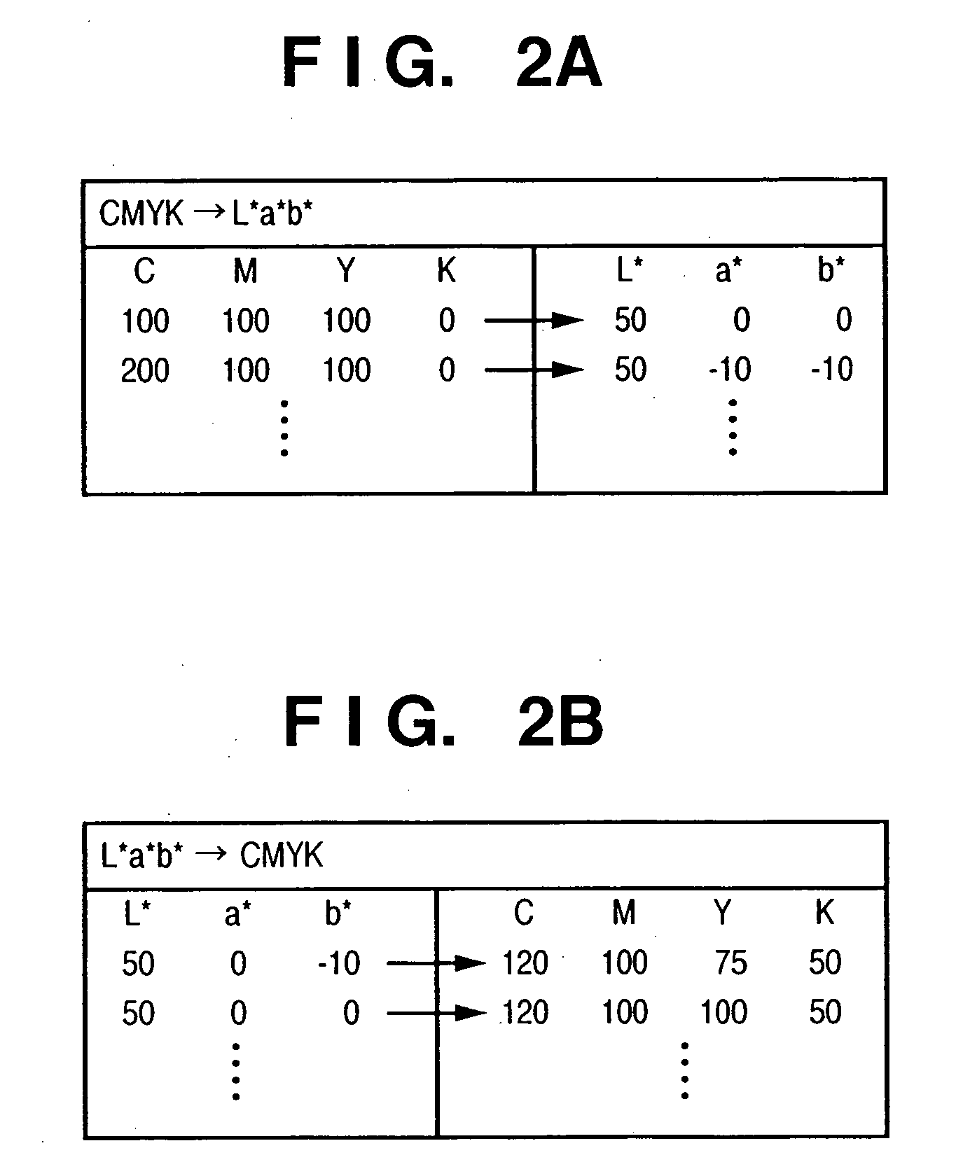
Since many ICC profile generation tools print and measure a large number of color patches and then make profile generation calculations, profile re-generation requires a long time. Hence, patch data are generated, calorimetric values corresponding to the patch data are obtained. Reference values of an Lab color space, which correspond to the patch data, are calculated using a conversion lookup table from a CMYK color space to the Lab color space, which is included in a profile. A conversion lookup table from the Lab color space to the CMYK color space, which is included in the profile, is updated using the calorimetric values and reference values.

Description

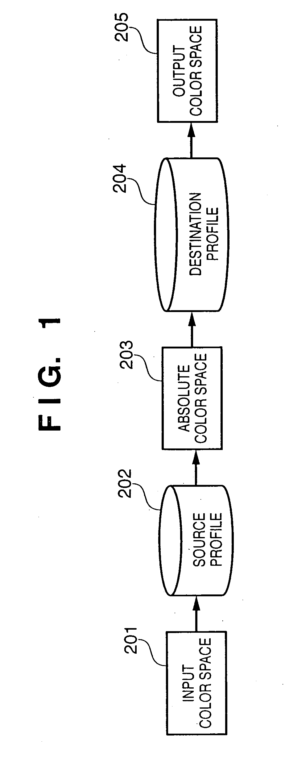
FIELD OF THE INVENTION [0001] The present invention relates to an image processing apparatus and its method and, more specifically, to color management. BACKGROUND OF THE INVENTION [0002] In recent years, color devices such as monitors, printers, and the like have prevailed, and the color management technique that manages color information is increasing in importance. Since display devices such as monitors and the like have different color gamuts from output devices such as printers and the like, color information of display devices cannot be handled as that of output devices intact. Hence, a color management system (to be referred to as a “CMS” hereinafter) becomes important. This system temporarily converts color information of an image input device into that in the absolute color space, and then converts the information in the absolute color space into that in a color space of an image output device, so as to convert and output color data of the image input device into color data...

Claims


Application Information

Patent Timeline
Patent Type & Authority Applications(United States)
IPC IPC(8): G06F15/00
CPCH04N1/6033G06T11/001
Inventor NAMIKATA, TAKESHI
Owner CANON KK
Why Eureka
Try Eureka