Method for preventing control packet loop and bridge apparatus using the method
a technology of control packets and bridges, applied in the field of control packet loop prevention methods and bridge apparatuses using the method, can solve the problem of taking a long time to switch a tree, and achieve the effect of preventing the occurrence of a control packet loop, reducing the time for switching a tree, and reducing the disconnecting time of the main signal
- Summary
- Abstract
- Description
- Claims
- Application Information
AI Technical Summary
Benefits of technology
Problems solved by technology
Method used
Image
Examples
first embodiment
[0067]FIG. 10 shows a flowchart showing a filter process performed by the BPDU loop detection / filter part 20 in a bridge (for example, bridge #2, #3) connected to a former root bridge (bridge #1, for example) according to a
[0068] This procedure starts when the BPDU loop detection / filter part 20 is notified of aging out from the age out detection part 24.
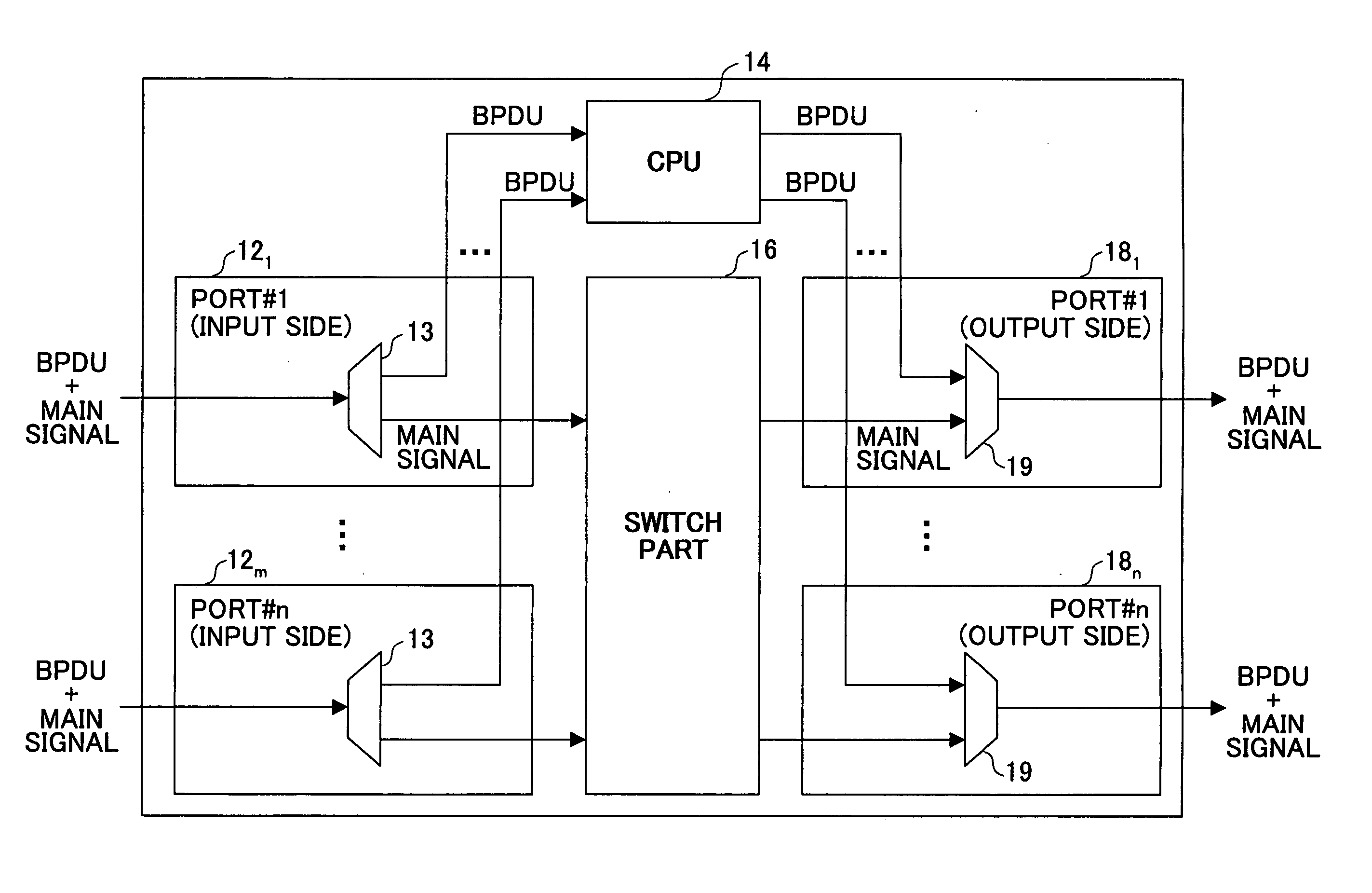
[0069] In the figure, the BPDU loop detection / filter part 20 receives a BPDU provided from one of the input port circuits 121˜12m in step S10. Then, in step S12, the BPDU loop detection / filter part 20 determines whether a root bridge ID in the received BPDU is the same as a root bridge ID before aging out that is held by the own bridge in step S12.
[0070] If they are the same, the BPDU loop detection / filter part 20 determines whether the message age in the received BPDU is 0 in step S14. If the message age is not 0 so that it can be determined that a bridge other than the former root bridge transferred the BPDU, the BPDU loop detect...
second embodiment
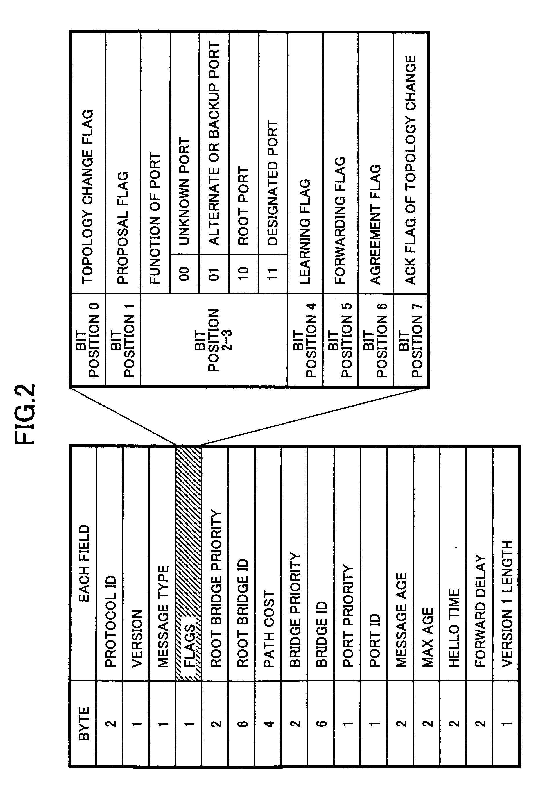
[0073]FIG. 11 is a flowchart showing a procedure of a filter process performed by the BPDU loop detection / filter part 20 in a bridge connected to the former root bridge according to a The difference between FIGS. 10 and 11 is as follows. It is determined whether the message age is 0 in step 14 in FIG. 10. On the other hand, it is determined whether a path cost is 0 in step S22 in FIG. 11. In FIG. 11, if the path cost is not 0, it is determined that the BPDU is transferred by a bridge other than the former root bridge so that it is determined that the BPDU loop occurs and the step goes to step S16. If the path cost is 0, it is determined that BPDU loop does not occur and the step goes to step S18.
[0074] The path cost is always 0 in a BPDU output from a root bridge, and a value is added to the path cost each time the BPDU is transferred by a bridge. Therefore, it can be determined whether the BPDU has passed through a bridge other than a root bridge. That is, if the path cost is not ...
third embodiment
[0075]FIG. 12 is a flowchart showing a procedure of a filter process performed by the BPDU loop detection / filter part 20 in a bridge connected to the former root bridge according to a The difference between FIGS. 10 and 12 is as follows. It is determined whether the message age in the BPDU is 0 in step 14 in FIG. 10. On the other hand, in FIG. 12, it is determined whether the message age is a predetermined value in step S24. If the message age is the predetermined value, it is determined that a bridge other than the former root bridge transferred the BPDU in step S24, then, in step S16, it is determined that a BPDU loop occurs. If the message age is not the predetermined value, it is determined that the BPDU loop does not exist and the step moves to the step S18.
[0076] In a network configuration shown in FIG. 6A, in a state of FIG. 6B, a message age in a BPDU transferred from the bridge #3 is 2 in the bridge #2 connected to the former root bridge #1. On the other hand, as shown in ...
PUM
 Abstract
Description
Claims
Application Information
 - R&D
- Intellectual Property
- Life Sciences
- Materials
- Tech Scout
- Unparalleled Data Quality
- Higher Quality Content
- 60% Fewer Hallucinations
Browse by: Latest US Patents, China's latest patents, Technical Efficacy Thesaurus, Application Domain, Technology Topic, Popular Technical Reports.
© 2025 PatSnap. All rights reserved.Legal|Privacy policy|Modern Slavery Act Transparency Statement|Sitemap|About US| Contact US: help@patsnap.com


