Analyzing tool and device

a technology of analyzing tools and analyzing equipment, which is applied in the direction of instruments, specific gravity measurement, laboratory glassware, etc., can solve the problems of complex photometric system, difficult to keep the length of the channel b>90/b>b uniform, and complicated operation of supplying sample liquid, etc., to achieve the effect of manufacturing costs and running costs

Inactive Publication Date: 2006-01-12
ARKRAY INC
View PDF4 Cites 24 Cited by
  • Summary
  • Abstract
  • Description
  • Claims
  • Application Information

AI Technical Summary

Benefits of technology

[0011] It is an object of the present invention to allow a sample liquid to be analyzed accurately by means of a simple configuration in which the work of supplying sample liquid to the analyzing tool is reduced while the size of the analyzing apparatus, the manufacturing costs and the running costs are controlled.

Problems solved by technology

However, in the analyzing tool 9A shown in FIG. 13A, the operation of supplying the sample liquid is complicated by the fact that the sample liquid needs to be supplied individually to each channel 90A via liquid inlet 91A.
However, as the number of channels 90B increases it becomes difficult to keep the length of channels 90B uniform.
This in turn means a more complex photometric system, a larger analyzing apparatus, higher manufacturing costs and higher running costs.
This complicates the device for analyzing sample liquids using the analyzing tool, leading to higher manufacturing costs and also to higher running costs because the analyzing tool needs to be rotated at high speeds.

Method used


Image

  • Analyzing tool and device
  • Analyzing tool and device
  • Analyzing tool and device

Examples


first embodiment

[0034] First, the present invention is explained with reference to FIGS. 1 through 10.

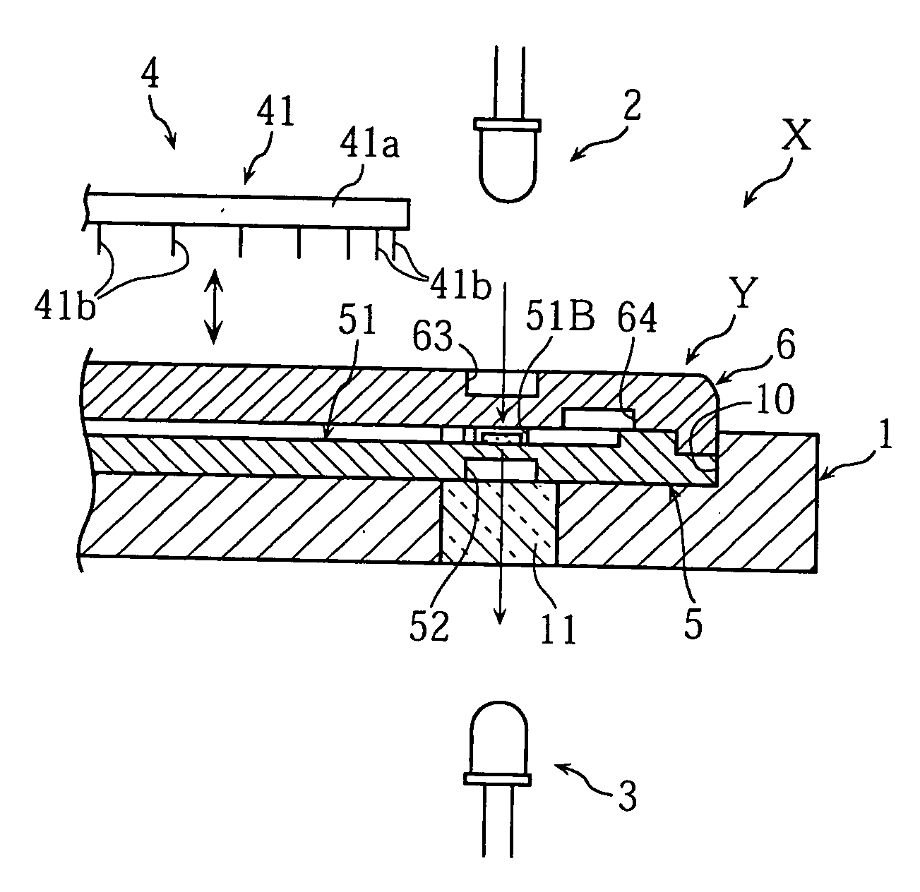
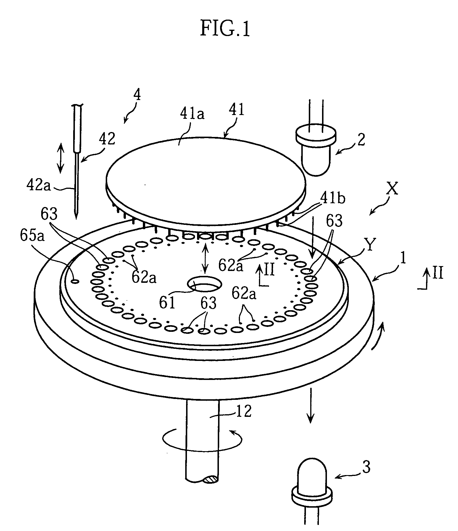
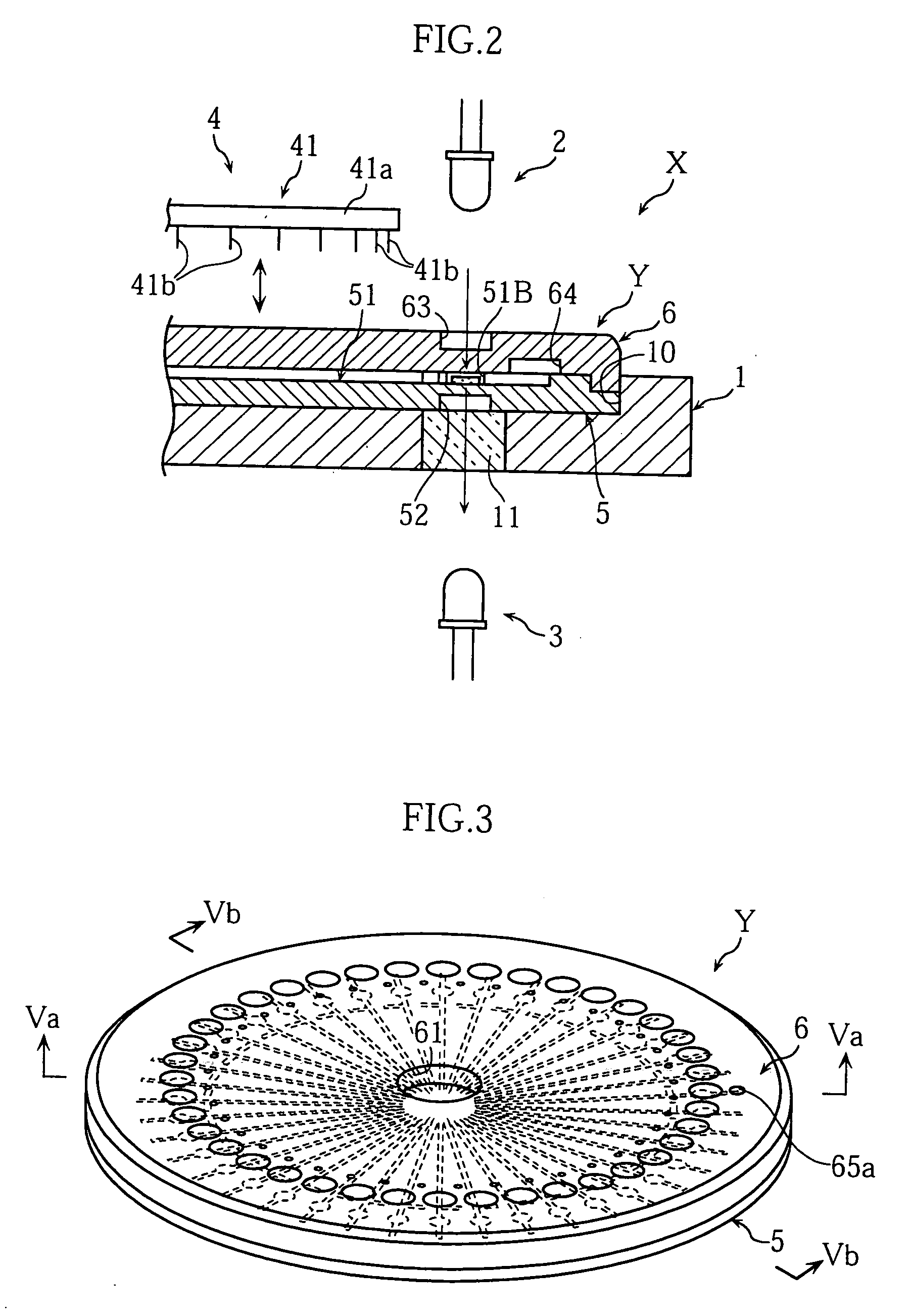
[0035] The analyzing apparatus X shown in FIGS. 1 and 2 is equipped with microdevice Y as an analyzing tool for purposes of analyzing a sample liquid, and is provided with mount 1 for mounting microdevice Y, light source 2, light detector 3 and opening mechanism 4.

[0036] The microdevice Y shown in FIGS. 3 through 5 provides the place for reaction, and has substrate 5, cover 6, adhesive layer 7 and separation membrane 8.

[0037] Substrate 5 is formed as a transparent disk, and has a form in which the outer circumferential edge is stepped down. As shown in FIGS. 5A and 6, substrate 5 has liquid receiver 50 in the central portion, multiple channels 51 which communicate with this liquid receiver 50, multiple grooves 52 and multiple branching channels 53.

[0038] Liquid receiver 50 serves the purpose of holding the sample liquid supplied to microdevice Y so that it can be introduced into channels 51. Liq...

second embodiment

[0075]FIG. 11 shows microdevice Ya according to the present invention.

[0076] In this microdevice Ya, multiple channels 51 are arranged radially extending linearly from liquid inlet 61 in the middle towards the outer edge, and reaction sites 51B are arranged on the same circle. In these respects it is the same as the microdevice Y explained previously (see FIG. 6). However, microdevice Ya differs from the microdevice Y explained previously (see FIG. 6) in that channels 51 communicate individually with exhaust holes 65A, with branching channels 53 and common channel 64 (see FIG. 6) omitted.

[0077] In this configuration, sample liquid introduced into channels 51 from liquid inlet 61 does not stop before reaction sites 51B but proceeds towards exhaust holes 65A by capillary action. In microdevice Ya, because liquid inlet 61 is positioned in the middle and reaction sites 51B are arranged on the same circle, the distance between liquid inlet 61 and each reaction site 51B is roughly the sa...

third embodiment

[0078]FIG. 12 shows microdevice Yb according to the present invention.

[0079] This microdevice Yb is similar to the microdevice Ya (see FIG. 11) explained above in that multiple reaction sites 51B are arranged on the same circumference on the outer peripheral portion of microdevice Yb. Microdevice Yb differs from the microdevice Ya (see FIG. 11) explained above in that multiple channels 51 are grouped as multiple collective channels 51D. Each collective channel 51D has common parts 51E and 51F and individual parts 51G which include reaction sites 51B. In each collective channel 51D, common parts 51E and 51F are common to channels 51 which make up this collective channel 51D.

[0080] In this configuration, sample liquid can be supplied all at once to multiple channels 51, and moreover if the number of individual parts 51G which are the final branches (and include reaction sites 51B) is small the length of channels 51 or in other words the distance between liquid inlet 61 and reaction s...


PUM

PropertyMeasurementUnit
depthaaaaaaaaaa
depthaaaaaaaaaa
width/height ratioaaaaaaaaaa

Abstract

This invention relates to technology for analyzing a specific component in a sample liquid, and provides an analyzing tool and an analyzing apparatus. Analyzing tool (Y) includes a liquid inlet (61) at a central portion of the tool and a plurality of channels (51) which communicate with liquid inlet (61) and move the sample liquid introduced through liquid inlet (61) by capillary action from the central portion towards a peripheral portion of the tool. Each channel (51) extends linearly for example from the central portion towards the peripheral portion, and the plurality of channels (51) are arranged radially.

Description

TECHNICAL FIELD [0001] The present invention relates to an analyzing tool and analyzing apparatus used for analyzing a sample liquid. BACKGROUND ART [0002] Methods of analyzing a sample liquid include for example methods in which a reaction liquid from the reaction of a sample liquid with a reagent is analyzed by optical means. When a sample liquid is analyzed by such means, an analyzing tool is used which provides a place for reaction. Some analyzing tools are equipped with a plurality of channels so that multiple analyses can be performed using one type of sample liquid, or so that multiple types of sample liquid can be subjected to the same analysis. [0003] Analyzing tools equipped with a plurality of channels include those having a rectangular configuration as shown in FIGS. 13A and 13B, in which the main parts of multiple channels 90A and 90B are arranged parallel to one another. On the other hand, there are analyzing tools having multiple channels arranged radially (for exampl...

Claims


Application Information

Patent Timeline
Patent Type & Authority Applications(United States)
IPC IPC(8): G01N21/00G01N31/20B01L3/00G01N1/00G01N21/03G01N21/25G01N33/48G01N35/00G01N35/02G01N35/10G01N37/00
CPCB01L3/5027B01L2300/0803B01L2300/0864B01L2300/1872B01L2400/0406G01N2035/00158G01N21/253G01N35/00069G01N35/025G01N35/10G01N2021/0346B01L2400/0409
Inventor TAGUCHI, TAKAYUKIKITAMURA, SHIGERUNODA, YUICHIROHARADA, TOSHIHIKO
Owner ARKRAY INC
Why Eureka
Try Eureka