Microfluidic system for chemical analysis

a microfluidic system and chemical analysis technology, applied in the field of chemical analysis systems, can solve the problems of conventional methods and apparatuses that require bulky components that are not efficiently miniaturized for downhole applications, and the loss of carbon dioxide and hydrogen sulfide can give misleading ph values

Active Publication Date: 2006-01-12
SCHLUMBERGER TECH CORP
View PDF13 Cites 64 Cited by
  • Summary
  • Abstract
  • Description
  • Claims
  • Application Information

AI Technical Summary

Benefits of technology

[0018] The instrument is particularly useful, for example, in oilfield applications for the detection of scale forming ions and dissolved gases and in water applications for the detection of hazardous chemicals. Chemical measurements of interest in the water business include, but is not limited to, pH and toxic chemicals, such as nitrate, arsenic and other heavy metals, benzene and other organic compounds. Chemical measurements of interest in the oilfield include, but is not limited to, the determination of pH, the detection of H2S and CO2, as well as scale forming ions such as Ca, Ba, Sr, Mg, and SO4.
[0019] Further features and applications of the present invention will become more readily apparent from the figures and detailed description that follows.

Problems solved by technology

Likewise, scaling out of salts and loss of carbon dioxide and hydrogen sulfide can give misleading pH values when laboratory measurements are made on downhole-collected samples.
Conventional methods and apparatuses require bulky components that are not efficiently miniaturized for downhole applications.
All associated analytical devices, including optical interrogation, power supply, reagent sources, and processing means, are typical laboratory-sized devices not suitable for remote interrogation.

Method used


Image

  • Microfluidic system for chemical analysis
  • Microfluidic system for chemical analysis
  • Microfluidic system for chemical analysis

Examples


Embodiment Construction

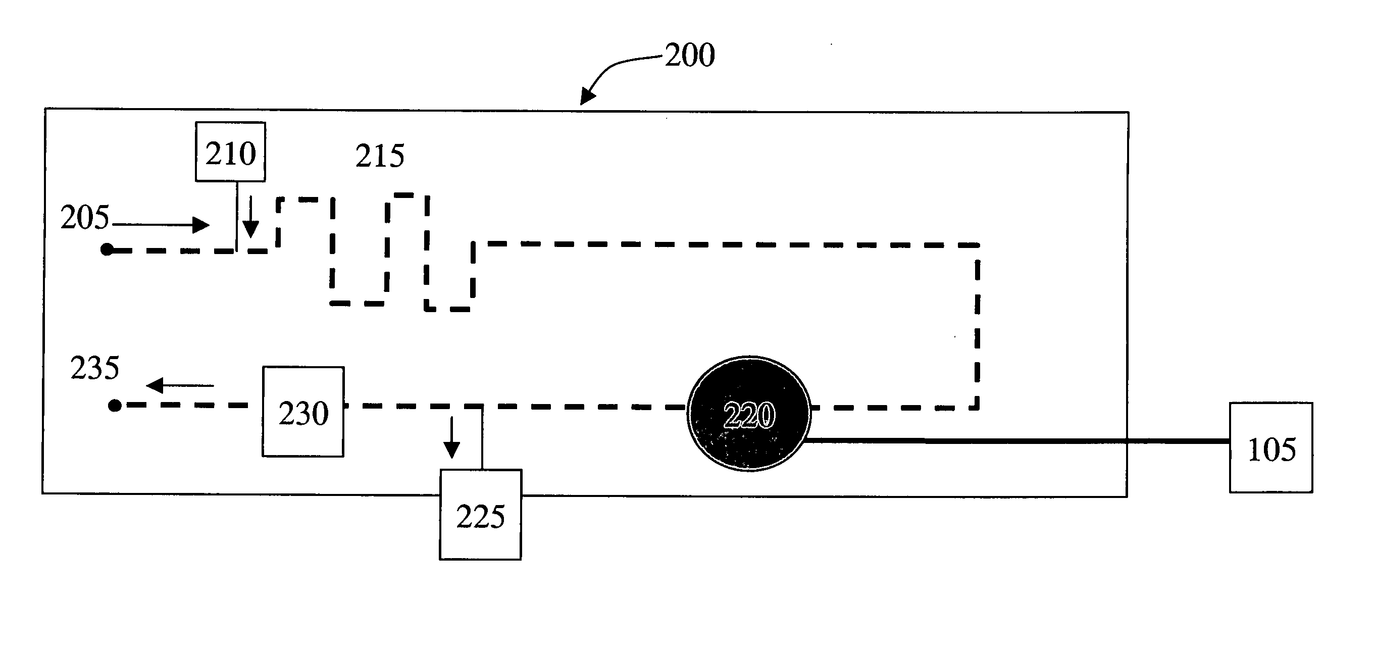
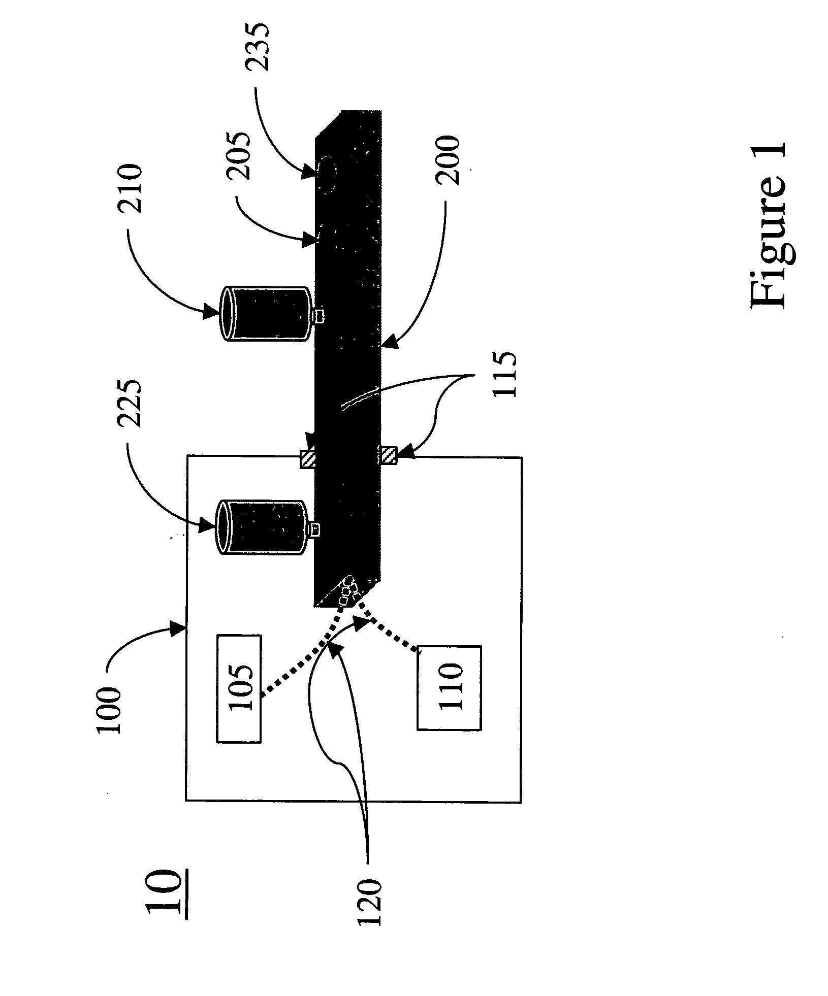
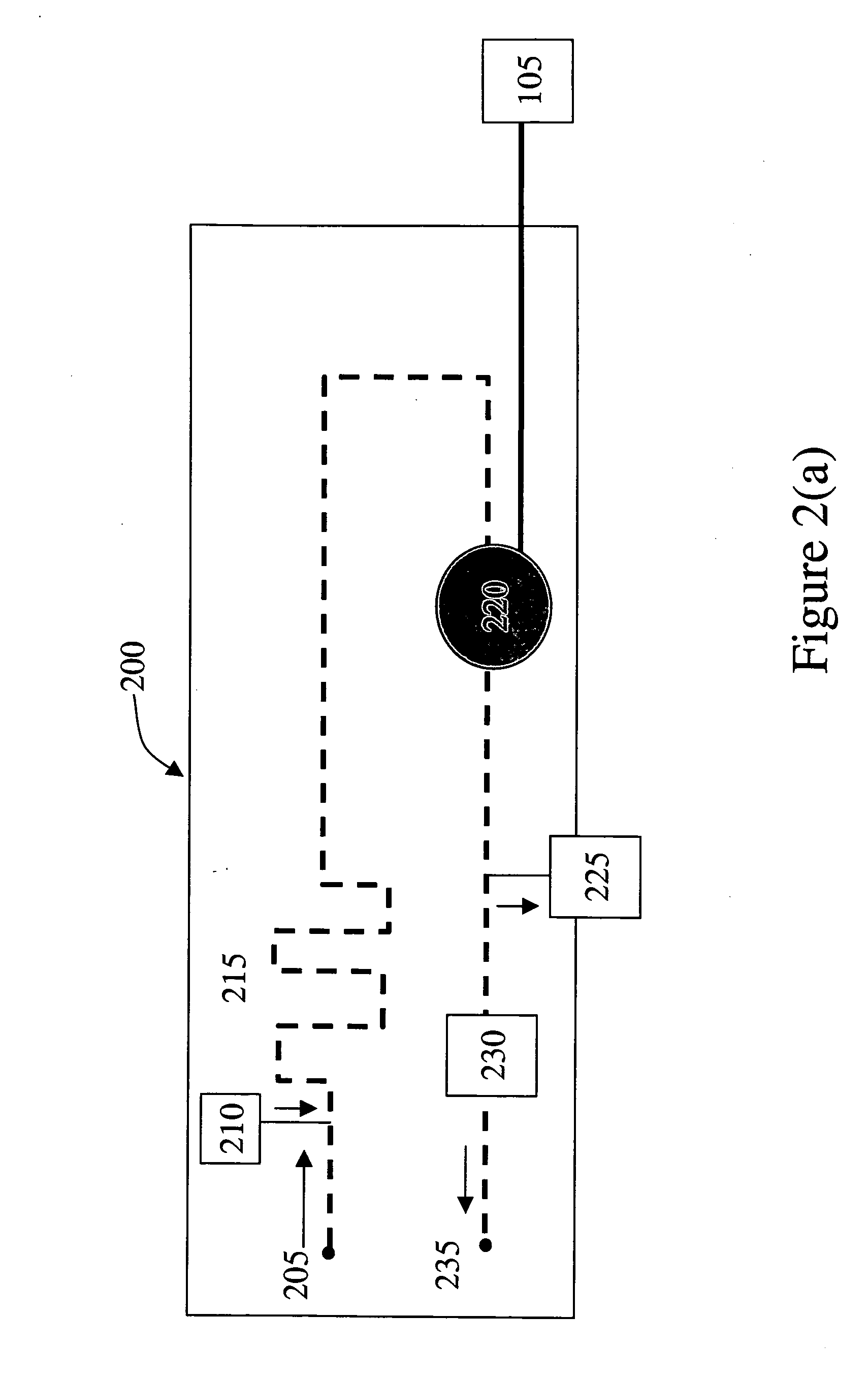
[0026]FIG. 1 is a schematic of the autonomous microfluidic system 10 of the present invention having a microfluidic substrate 200 in communication with a housing 100. Preferably, the substrate 200 is hermetically sealed to the housing 100 such that the sample inlet 205 extends outside of the housing 100 and the electrical connections 120 are within the housing 100. The housing 100 further includes a power supply 105 and control electronics 110 in electrical connection with the substrate 200. It is noted that while reservoir 210 is shown in this figure outside the housing 100 and the waste collector 225 is shown inside the housing 100, the location of these components relative to the housing will depend on the desired configuration of the system. Alternatively, the waste fluid may be discharged via outlet 235. Accordingly, the configuration ofFIG. 1 is intended to be illustrative and non-limiting. Most preferably, the housing 100 is bonded 115 directly to the substrate 200 avoiding e...


PUM

PropertyMeasurementUnit
pressureaaaaaaaaaa
opticalaaaaaaaaaa
optical interrogationaaaaaaaaaa

Abstract

A microfluidic system for performing fluid analysis is described having: (a) a submersible housing having a fluid analysis means and a power supply to provide power to said system; and (b) a substrate for receiving a fluid sample, having embedded therein a fluid sample inlet, a reagent inlet, a fluid sample outlet, and a mixing region in fluid communication with the fluid sample inlet, the reagent inlet, and the fluid sample outlet, and wherein the substrate includes a fluid drive means for moving the fluid sample through the substrate, and wherein the substrate interconnects with the housing. At least a portion of the fluid analysis means may be embedded in the substrate.

Description

FIELD OF THE INVENTION [0001] The present invention relates to a chemical analysis system and, more particularly, to the use of self-supporting microfluidic systems for chemical analysis of water or mixtures of water and oil. BACKGROUND [0002] In oil well evaluation and aquifer management, quantitative analyses of formation fluid are typically performed in a laboratory environment, the samples having been collected remotely. Standard laboratory procedures are available for quantitative analyses by adding a reagent to chemically react with a specific target species in a sample to cause detectible changes in fluid property such as color, absorption spectra, turbidity, electrical conductivity, etc. See Vogel, A. I., “Text-Book of Quantitative Inorganic Analysis, 3rd Edition”, Chapter 10-12, John Wiley, 1961, incorporated by reference herein in its entirety. Such changes in fluid property may be caused, for example, by the formation of a product that absorbs light at a certain wavelengt...

Claims


Application Information

Patent Timeline
Patent Type & Authority Applications(United States)
IPC IPC(8): G01N21/00B01L3/00G01N27/00G01N31/00
CPCB01L3/502707B01L3/50273B01L3/502715
Inventor SALAMITOU, PHILIPPEWONG, JOYCERAGHURAMAN, BHAVANISHAH, JAGDISHVAN HAL, RONALD E. G.SCHROEDER, ROBERT J.TABELING, PATRICK JEAN RENE
Owner SCHLUMBERGER TECH CORP
Why Eureka
Try Eureka