Shift fork position detecting device for manual transmission

a technology of shift fork and shift position, which is applied in the direction of mechanical control devices, process and machine control, instruments, etc., can solve the problems of difficult adjustment of the space between the magnet b>62/b> and the magnetic sensor b>64/b>, and achieves easy assembly, easy adjustment of the space, and increase the support rigidity of the magnet

Inactive Publication Date: 2006-01-19
NISSAN MOTOR CO LTD
View PDF8 Cites 32 Cited by
  • Summary
  • Abstract
  • Description
  • Claims
  • Application Information

AI Technical Summary

Benefits of technology

[0009] It is accordingly an object of the present invention to provide a shift fork position detecting device for a twin clutch manual transmission which is free from the above-descri

Problems solved by technology

Further, since magnet 72 is mounted on shift fork 56 and magnetic sensor 64 is mounted on the transmission c

Method used


Image

  • Shift fork position detecting device for manual transmission
  • Shift fork position detecting device for manual transmission
  • Shift fork position detecting device for manual transmission

Examples


Embodiment Construction

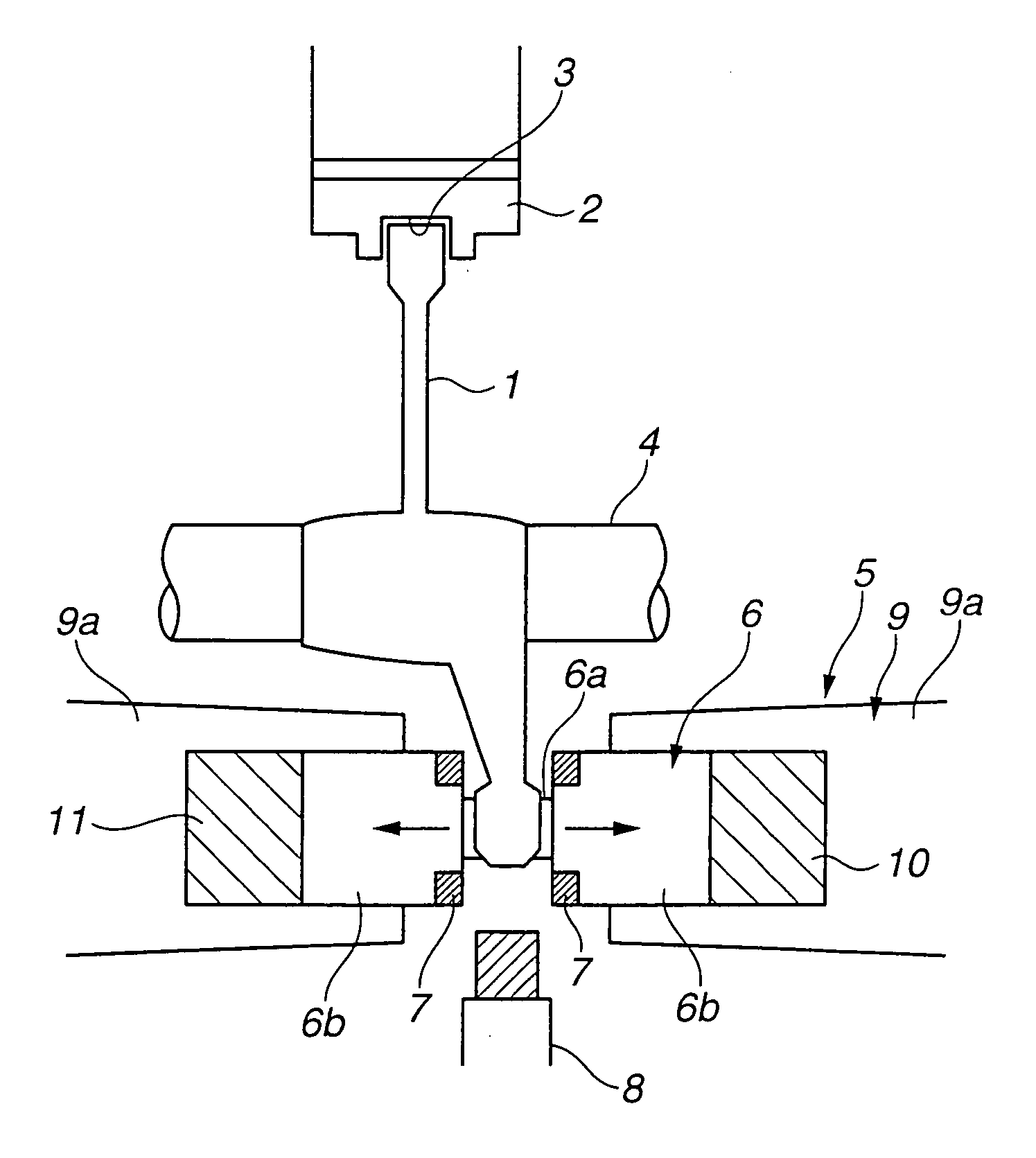
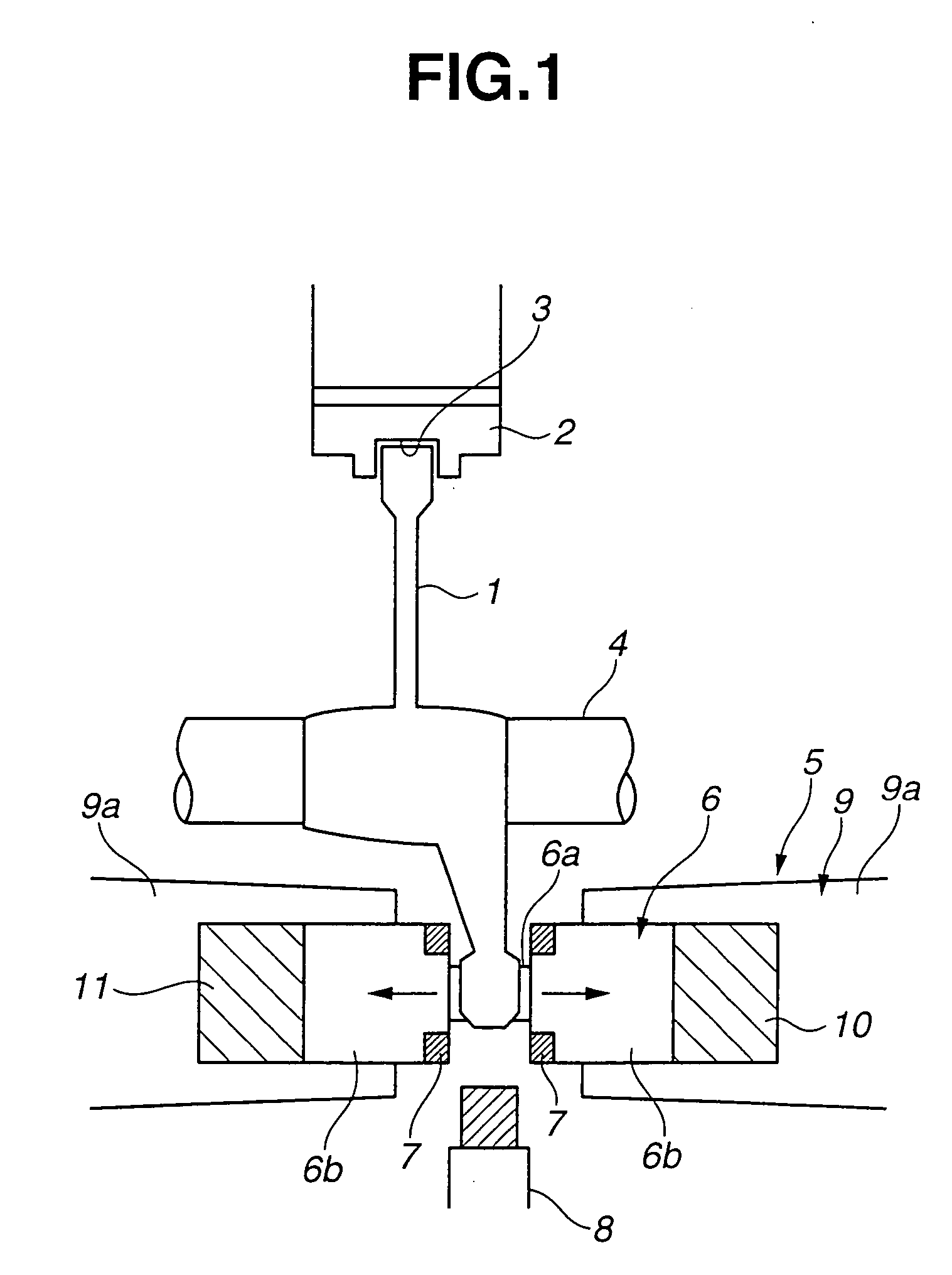
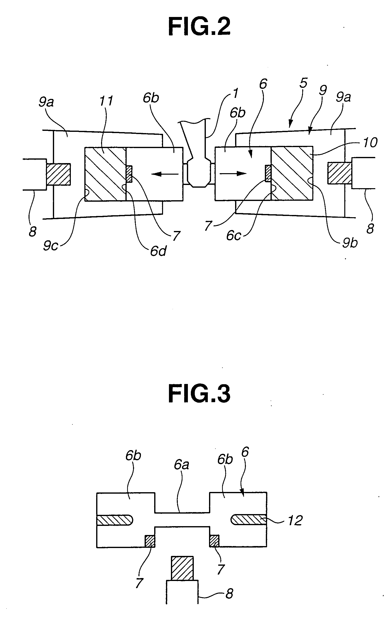
[0019] Referring first to FIG. 1, a shift fork position detecting device for a twin clutch manual transmission according to an embodiment of the present invention will be described. In FIG. 1, shift fork 1 is engaged in outer circumferential grove 3 of coupling sleeve 2 that constitutes a synchronizer of a twin clutch manual transmission while being slidably mounted to shift shaft 4 disposed in parallel with the center axis of coupling sleeve 2. Actuator 5 has stationary main body 9 and reciprocal output member 6 operatively connected to shift fork 1 for moving shift fork 1 axially thereof. Output member 6 has a pair of sliding sections 6b and connecting section 6a between sliding sections 6b. Output member 6 is coupled at connecting section 6a with shift fork 1. Main body 9 of actuator 5 has a pair of cylinder sections 9a in which respective sliding sections 6b of output member 6 are slidably installed.

[0020] Two permanent magnets 7 in the form of a circular ring are embedded in s...


PUM


Abstract

A shift fork position detecting device for a manual transmission is provided. The manual transmission includes a coupling sleeve constituting a synchronizer, a shift fork movable with the coupling sleeve and an actuator for moving the shift fork. The actuator has a stationary main body and a reciprocal output member operatively connected to the shift fork. The shift fork position detecting device includes a magnet mounted on the output member of the actuator, and a magnetic sensor mounted on the main body of the actuator to cooperate with the magnet for detecting the position of the shift fork.

Description

BACKGROUND OF THE INVENTION [0001] The present invention relates in general to a manual transmission and particularly to a twin clutch manual transmission having automatic clutches for respective gear range groups and useful for performing automatic shifting by switching of the automatic clutches between an engaged condition and a disengaged condition and by alternative selection of a gear range between the gear range groups. More particularly, the present invention relates to a shift fork position detecting device for a manual transmission such as a twin-clutch manual transmission. [0002] Heretofore, such a twin clutch manual transmission is known as disclosed in Unexamined Japanese Patent Publication No. 8-320054. The twin clutch manual transmission includes a first input shaft and second input shaft to which rotational power of an engine is selectively supplied by way of respective automatic transmissions. The second input shaft is hollow and is rotatably fitted on the first shaf...

Claims


Application Information

Patent Timeline
IPC IPC(8): F16H63/00
CPCF16H59/70F16H63/3023Y10T74/20177G01D5/145Y10T74/20183F16H63/32
Inventor HARA, TOMOYUKIGOTOH, SATOSHI
Owner NISSAN MOTOR CO LTD
Why Eureka
Try Eureka