Formation of a wire bond with enhanced pull

a technology of enhanced pull and wire bonding, which is applied in the direction of manufacturing tools, non-electric welding apparatus, solid-state devices, etc., can solve the problems of coiling force on the wire loop, and achieve the effect of more consistent loop profiles and greater repeatability

Inactive Publication Date: 2006-01-19
ASM TECH SINGAPORE PTE LTD
View PDF10 Cites 11 Cited by
  • Summary
  • Abstract
  • Description
  • Claims
  • Application Information

AI Technical Summary

Benefits of technology

[0008] It is therefore an object of the invention to seek to provide a method of forming wire loops with more consistent loop profiles and greater repeatability as compared to the aforesaid prior art, especially but not exclusively for low loop packages.

Problems solved by technology

A problem with this prior art motion profile to form the stitch bond 20 is that when the bonding wire first touches the second bonding surface 14 at bonding point E, there is a recoil force on the wire loop 10 because of the shock of the impact force of the capillary on the second bonding surface 14.
While the vertical pull and table pull motions may be sufficient to reduce the recoil effect for common and undemanding applications, they are insufficient for bonding ultra low wire loop packages, where a height differential between the first bonding point on the first bonding surface 12 to the second bonding point on the second bonding surface 14 is less than 3.0 mils and / or the distance between the first and second bonding points or wire length is 3.5 mm or longer.

Method used


Image

  • Formation of a wire bond with enhanced pull
  • Formation of a wire bond with enhanced pull
  • Formation of a wire bond with enhanced pull

Examples


Embodiment Construction

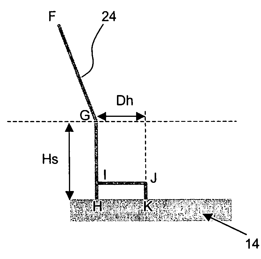
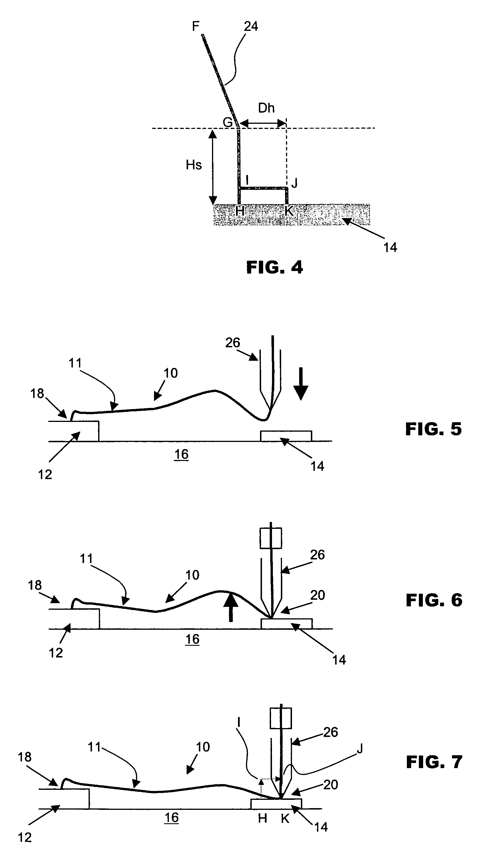
[0019]FIG. 4 is a side view of a motion profile 24 of a bonding tool in the form of a capillary attached to an ultrasonic transducer according to the preferred embodiment of the invention. The capillary of the bonding tool forms a first bond from a bonding wire fed from the bonding tool at a first bonding point. The capillary then extends the bonding wire from the first bond while it is moved from the first bonding point towards a second bonding point in a loop trajectory so as to form a loop profile. From a top of a trajectory loop at point F indicated in FIG. 4, the capillary moves towards the second bonding surface 14 until a search height Hs, where it is positioned over a second bonding surface 14 at point G.

[0020] From point G, the capillary is driven down vertically in substantially a straight line to make a first contact on a support surface on the second bonding surface 14 at point H. The support surface at point H is preferably spaced from the second bonding point K in the...


PUM

PropertyMeasurementUnit
heightaaaaaaaaaa
distanceaaaaaaaaaa
diameteraaaaaaaaaa

Abstract

A method of forming a wire connection using a bonding tool is provided. A first bond is first formed from a bonding wire fed from the bonding tool at a first bonding point. The bonding wire is then extended from the first bond while moving the bonding tool from the first bonding point towards a second bonding point. Thereafter, the bonding wire is mechanically deformed by contacting the bonding tool against a support surface and the bonding tool is moved in a direction away from the first bond to pull the bonding wire before forming a second bond with the bonding tool.

Description

FIELD OF THE INVENTION [0001] The invention relates to the formation of wire bonds for making electrical connections, in particular, to the formation of wire bonds between bonding surfaces of semiconductor devices. BACKGROUND AND PRIOR ART [0002] When making an electrical connection between bonding surfaces of semiconductor devices, ultrasonic energy may be provided to a bonding wire on the bonding surface to form the bond, either at room temperature or at elevated temperatures. There are typically two bonding points for a single bonding wire, and the distance between the two bonding points is conventionally referred to as the wire length. In a type of wire bonding process called ball-bonding, a first bond comprises a ball bond and a second bond comprises a stitch bond. [0003] During the ball-bonding process, a molten ball that is formed by melting a tail end of the wire is placed at the first bonding point to form the ball bond and the wire is extended from the ball bond by a capil...

Claims


Application Information

Patent Timeline
Patent Type & Authority Applications(United States)
IPC IPC(8): B23K31/00
CPCB23K20/004H01L24/48H01L2224/85099H01L2924/01033H01L2924/01019H01L2924/01006H01L2924/00014H01L2924/20752H01L2924/01005H01L2224/85399H01L2224/85205H01L2224/85181H01L2224/78301H01L2224/48465H01L2224/48247H01L2224/48091H01L2224/4809H01L2224/45015H01L2224/05599H01L24/85H01L24/78H01L2224/45099H01L2924/00H01L2224/05554
Inventor LEE, WAI WAHCHO, CHIA YEN
Owner ASM TECH SINGAPORE PTE LTD
Why Eureka
Try Eureka