
Systems and methods for testing radio frequency identification tags

Inactive Publication Date: 2006-01-19
SYMBOL TECH INC
View PDF66 Cites 32 Cited by
  • Summary
  • Abstract
  • Description
  • Claims
  • Application Information

AI Technical Summary

Benefits of technology

[0010] Each tag in the array may be tested in this manner, by stopping the emission of radiation to the tag by the corresponding radiation source during testing of the tag.
[0011] According to a second embodiment, an array of blocking elements is present. Each blocking element in the array corresponds to a tag in a plurality of tags. A blocking element in the array controllably inhibits radiation emitted by a radiation source to allow operation of an integrated circuit of its corresponding tag. A first blocking element in the array inhibits radiation from being incident upon its corresponding tag. The tag corresponding to the first blocking element is tested, as its operation is not inhibited by radiation. Thus, the tag may be reliably tested in an isolated manner, even in the presence of other tags.
[0012] Each tag in the array may be tested in this manner, by inhibiting radiation from being incident upon the tag by the corresponding blocking element during testing of the tag.

Problems solved by technology

Currently, radio frequency identification (RFID) tags manufactured in high volume are difficult to test.
For example, in the presence of a large number of tags, such as in a tag assembly line, it may be difficult to isolate an individual tag for testing.
Thus, the effectiveness of the tag test may be diminished by the possibility of responses from the other tags in range.
Spatial isolation of a particular tag under test is difficult to accomplish.
However, this is complex, expensive, and often does not work sufficiently to read one and only one tag.

Method used


Image

  • Systems and methods for testing radio frequency identification tags
  • Systems and methods for testing radio frequency identification tags
  • Systems and methods for testing radio frequency identification tags

Examples


Embodiment Construction

I. Overview

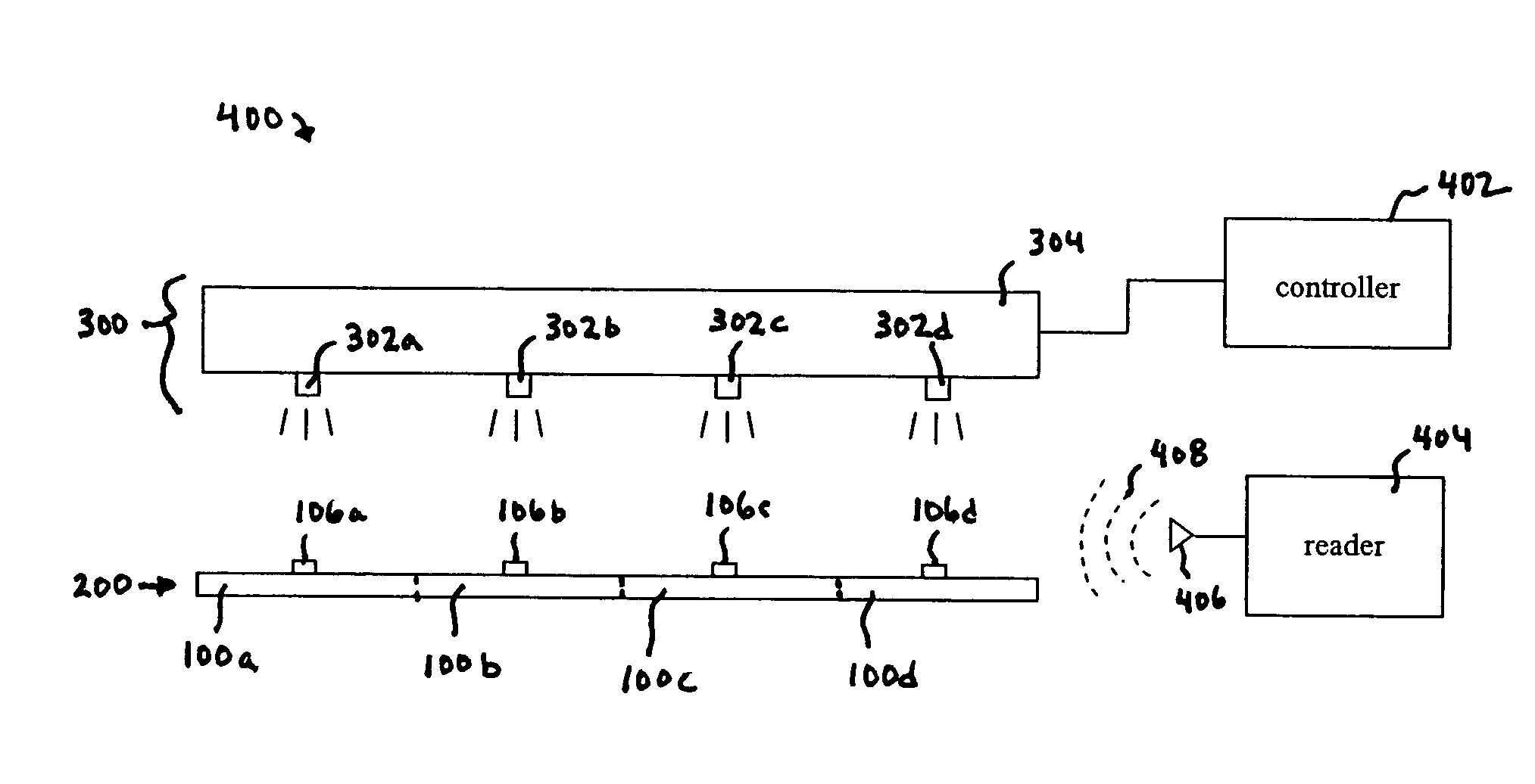
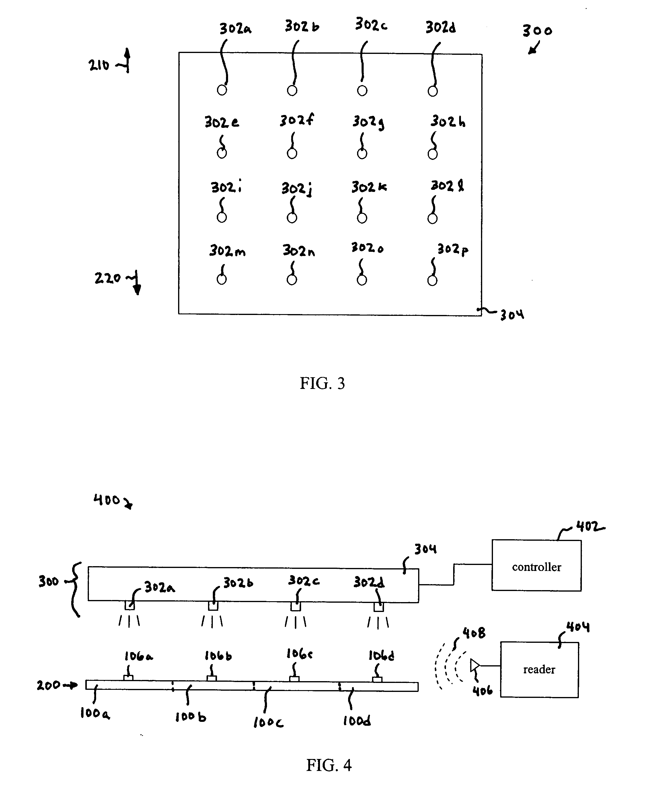
[0026] The present invention relates to the testing of individual RFID tags located in a group of RFID tags. Embodiments of the present invention use radiation sources to inhibit operation of tags. A single tag (or multiple tags, depending on the type of test) is not radiated, and thus its operation is not inhibited. This “isolated” tag is then tested, by any desired technique, for proper operation. For example, in an embodiment, the isolated tag may be tested by a reader that transmits a communication signal directed to the isolated tag, including “near-field” read or “far-field” read configurations.

[0027] According to embodiments of the present invention, individual RFID tags located in a group of tags may be isolated and tested that are much less than a wavelength of the communication signal away from each other.

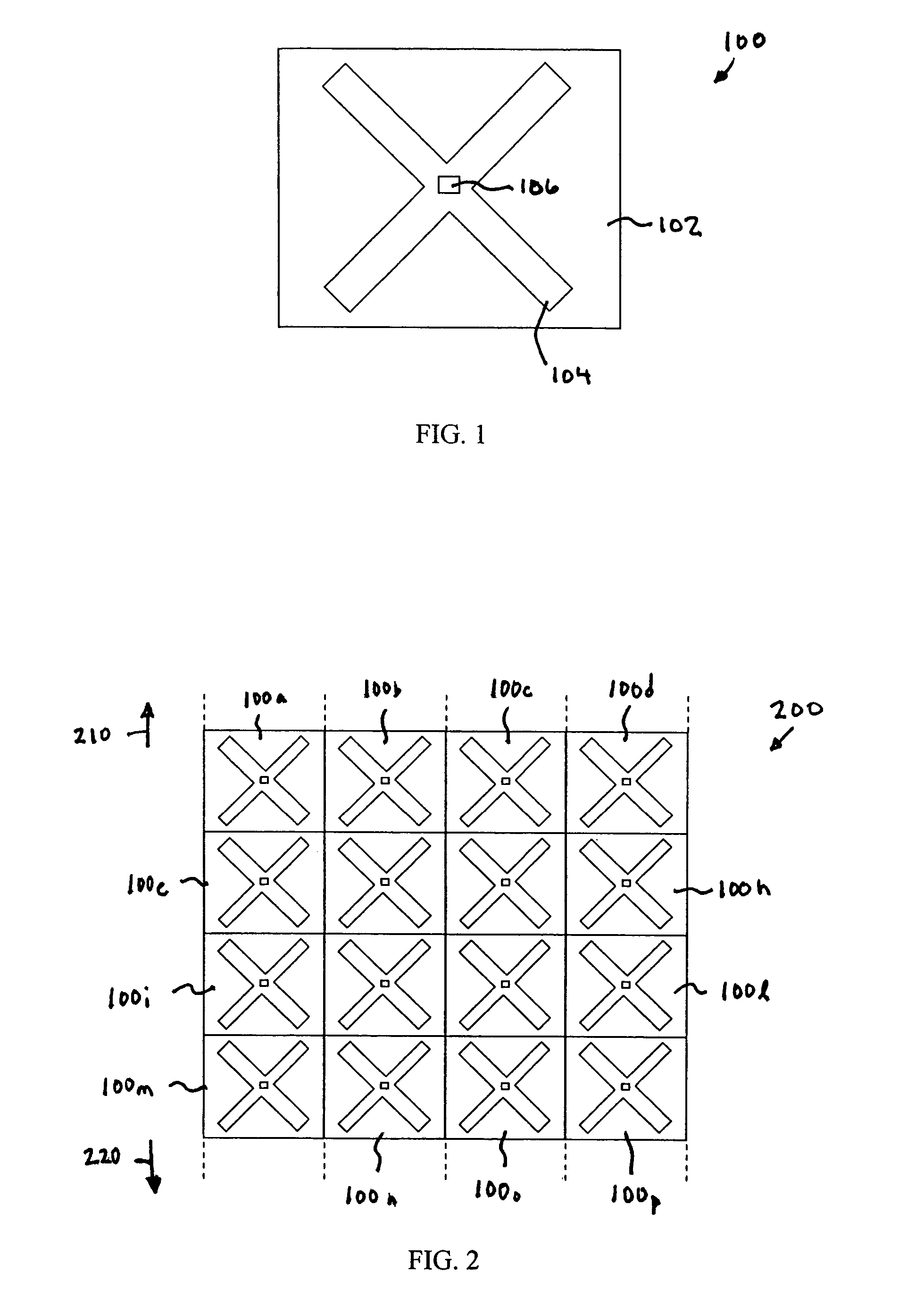
[0028] The present invention is applicable to any type of RFID tag. FIG. 1 shows a plan view of an example radio frequency identification (RFID) tag 100. Tag...


PUM


Abstract

Methods and systems for testing tags in volume are described. According to a first embodiment, an array of radiation sources is present. Each radiation source in the array corresponds to a tag in a plurality of tags. A plurality of radiation sources in the array controllably emit radiation to their corresponding tag to inhibit operation of an integrated circuit of their corresponding tag. A first radiation source in the array does not emit radiation to its corresponding tag. The tag corresponding to the first radiation source is tested. In a second embodiment, an array of blocking elements is present. Each blocking element in the array corresponds to a tag in a plurality of tags. The blocking elements in the array controllably inhibit radiation from being incident upon corresponding tags. A first blocking element in the array inhibits radiation from being incident upon its corresponding tag. The tag corresponding to the first blocking element is tested.

Description

CROSS-REFERENCE TO RELATED APPLICATION [0001] This application claims the benefit of U.S. Provisional Application No. 60 / 583,402, filed Jun. 29, 2004 (Atty. Dkt. No. 1689.0630000), which is incorporated herein by reference in its entirety.BACKGROUND OF THE INVENTION [0002] 1. Field of the Invention [0003] The present invention relates to radio frequency identification tags, and more specifically to testing of radio frequency identification tags. [0004] 2. Background Art [0005] Currently, radio frequency identification (RFID) tags manufactured in high volume are difficult to test. For example, in the presence of a large number of tags, such as in a tag assembly line, it may be difficult to isolate an individual tag for testing. In other words, a standard read signal used to test a tag in a population of tags not only powers the tag under test, but the other tags in range. Thus, the effectiveness of the tag test may be diminished by the possibility of responses from the other tags in ...

Claims


Application Information

Patent Timeline
IPC IPC(8): G01R31/302G01M19/00H04Q5/22G01M99/00
CPCG01R31/3025G01R31/303G06K17/00G06K7/10019G06K7/0095
Inventor SHANKS, WAYNE E.
Owner SYMBOL TECH INC
Learn More