
Tire air pressure monitoring system

a technology of air pressure monitoring and tires, which is applied in the direction of burglar alarm mechanical actuation, instruments, transportation and packaging, etc., can solve the problem of inability to identify the position of the four tires

Inactive Publication Date: 2006-01-19
NISSAN MOTOR CO LTD
View PDF7 Cites 43 Cited by
  • Summary
  • Abstract
  • Description
  • Claims
  • Application Information

AI Technical Summary

Benefits of technology

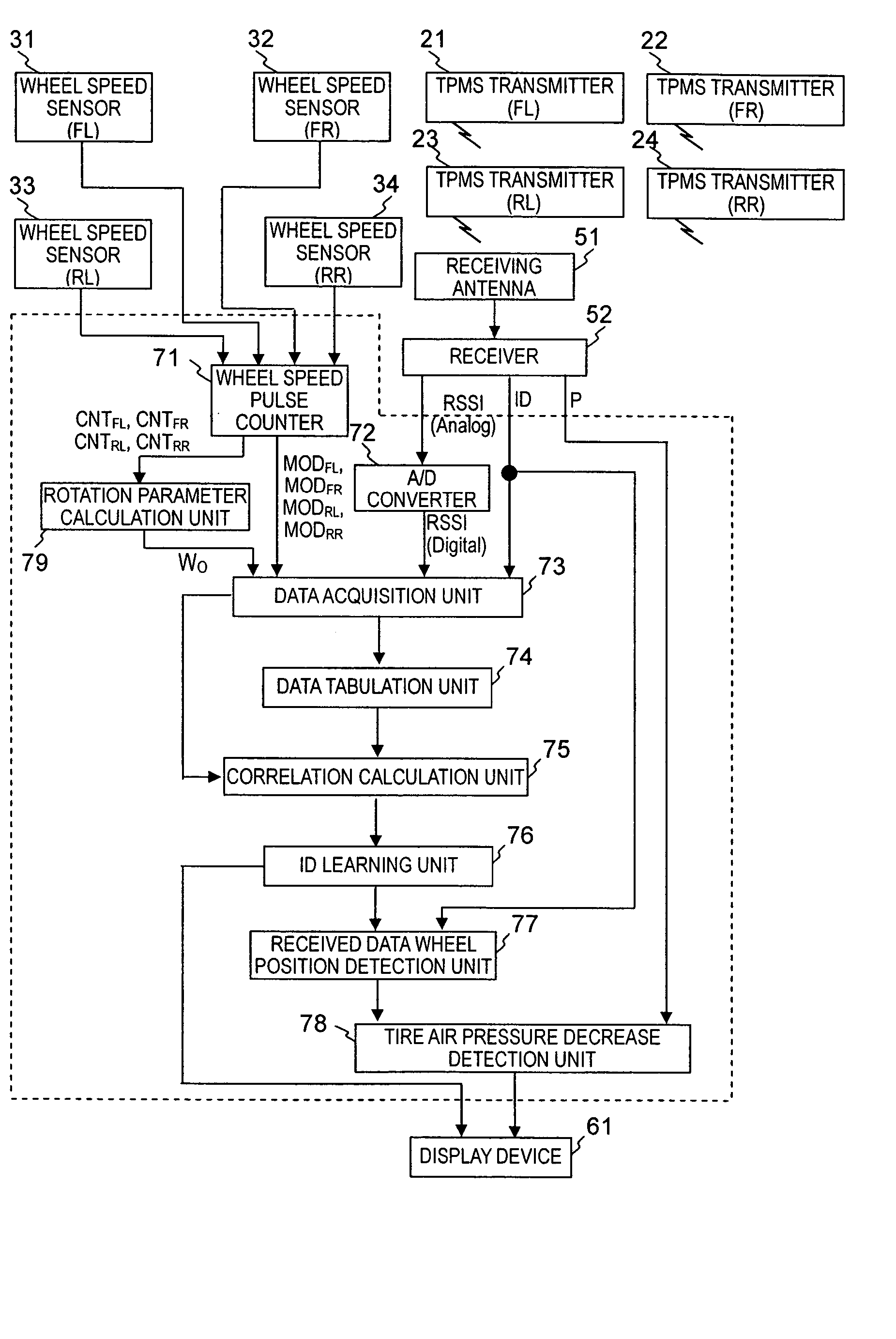
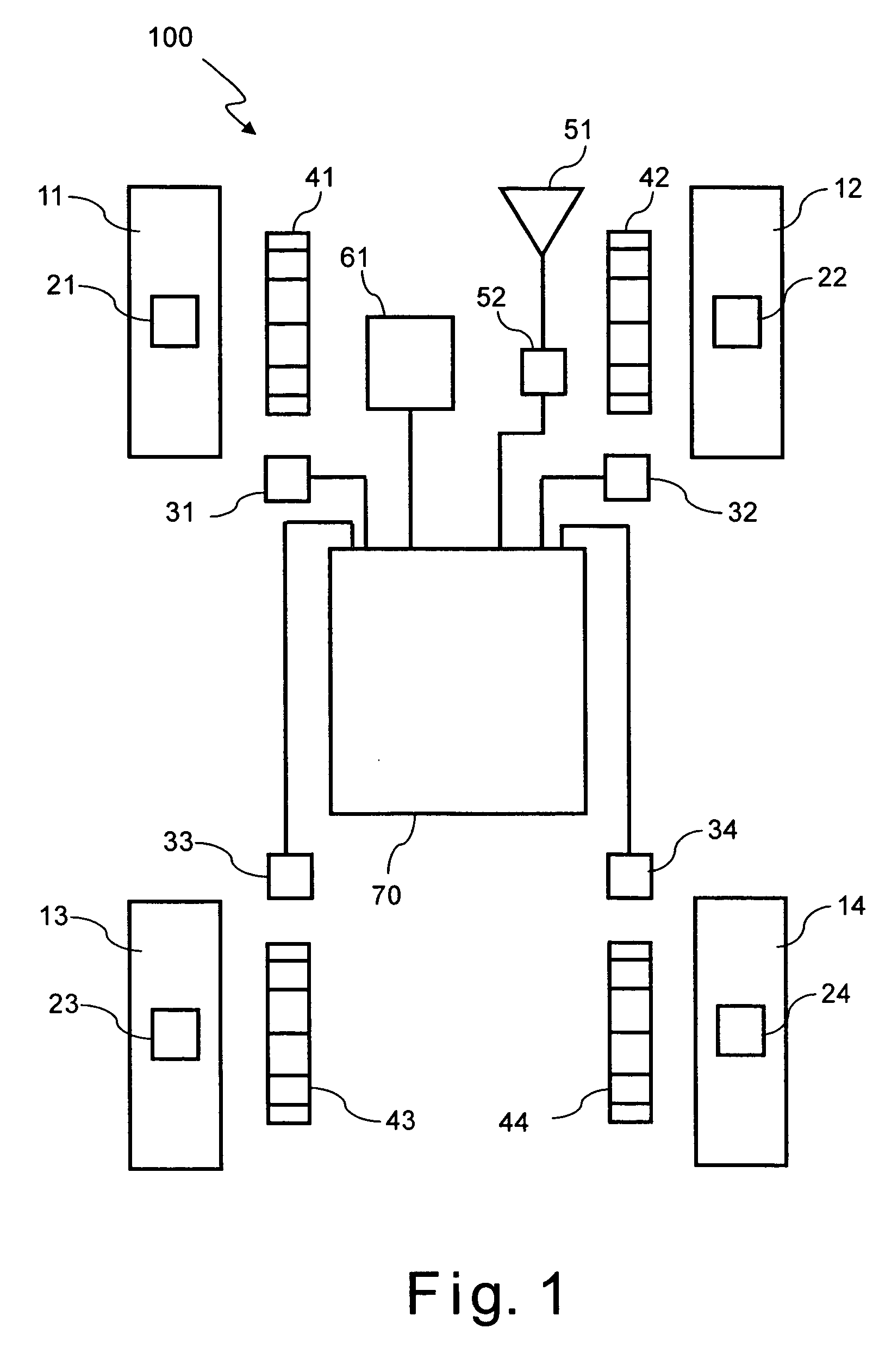
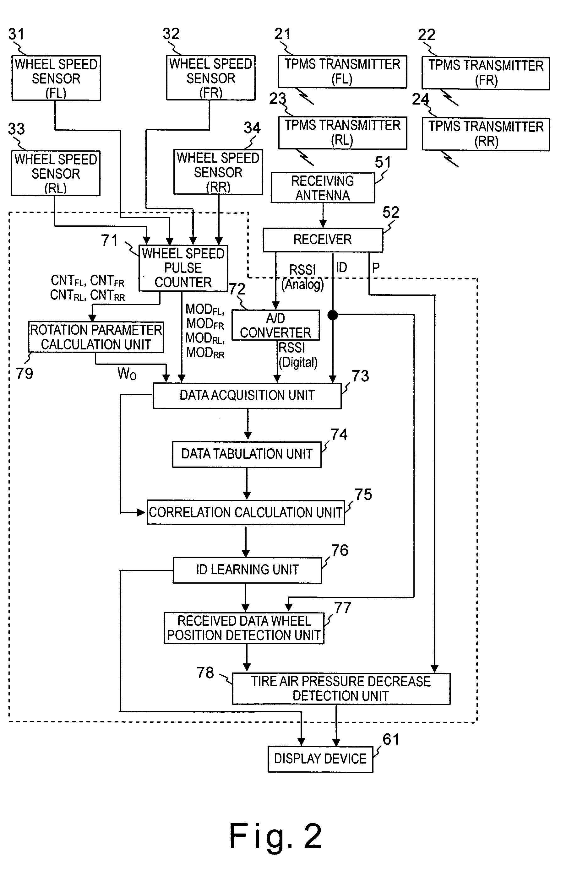
[0008] The present invention was designed in view of the problems described above. One object of the present invention is to provide a tire air pressure monitoring system in which there is no need to store the variation pattern of the radio wave strength in advance, and the positions of the wheels can be reliable estimated even if various tires or wheels with different shapes or materials are mounted to the vehicle.

Problems solved by technology

As a result, there is a possibility that the positions of the four tires cannot be identified based on the radio wave transmitted from each transmitter.

Method used


Image

  • Tire air pressure monitoring system
  • Tire air pressure monitoring system
  • Tire air pressure monitoring system

Examples


second embodiment

[0118] Referring now to FIG. 15, a tire air pressure monitoring system in accordance with a second embodiment will now be explained. In view of the similarity between the first and second embodiments, the parts of the second embodiment that are identical to the parts of the first embodiment will be given the same reference numerals as the parts of the first embodiment. Moreover, the descriptions of the parts of the second embodiment that are identical to the parts of the first embodiment may be omitted for the sake of brevity.

[0119] The tire air pressure monitoring system of the second embodiment is basically identical to the tire air pressure monitoring system of the first embodiment except that a plurality of tire air pressure sensors 121 to 124 instead of the transmitters 21 to 24 of the first embodiment. More specifically, each of the tire air pressure sensors 121 to 124 includes a transmitter that is configured to generate a signal itself using power from a battery B and to tr...


PUM


Abstract

A tire air pressure monitoring system is provided that comprises a transmitting device, a receiving device, and a tire identification number registration device. The transmitting device is mounted on a wheel of a vehicle, and configured and arranged to wirelessly transmit a signal indicative of at least tire air pressure information of a tire coupled to the wheel and a tire identification number assigned to the wheel. The receiving device is mounted on the vehicle, and configured and arranged to receive the signal transmitted from the transmitting device. The tire identification number registration device is configured to estimate a position of the wheel with respect to the vehicle based on correlation information corresponding to an extent of a correlation between strength of the signal and a tire rotational angle of the wheel, and to register the tire identification number with the position of the wheel.

Description

CROSS-REFERENCE TO RELATED APPLICATIONS [0001] This application claims priority to Japanese Patent Application No. 2004-208401. The entire disclosure of Japanese Patent Application No. 2004-208401 is hereby incorporated herein by reference. BACKGROUND OF THE INVENTION [0002] 1. Field of the Invention [0003] The present invention relates to a tire air pressure monitoring system configured and arranged to estimate positions of wheels with respect to a vehicle based on electrical waves received by a receiver that is configured and arranged to receive radio waves from transmitters respectively coupled to the wheels. [0004] 2. Background Information [0005] Japanese Laid-Open Patent Publication No. 2003-175711 discloses a conventional tire air pressure monitoring system in which a reception device for processing received data is configured and arranged to identify a wheel provided with a transmitter when the transmitter sends radio wave based on a voltage pattern induced in a receiving an...

Claims


Application Information

Patent Timeline
IPC IPC(8): B60C23/00G08B21/00
CPCB60C23/061B60C23/0416
Inventor HIRAI, TORU
Owner NISSAN MOTOR CO LTD
Learn More