
Dynamic monitor system

a monitor system and dynamic technology, applied in the field of dynamic monitor systems, can solve the problems of expensive cost, tedious wiring rearrangement, and inconvenient adjustment, so as to save the border space occupied by activating multiple browsers, execute more effectively, and easily adjust.

Inactive Publication Date: 2006-01-19
WINBOND ELECTRONICS CORP
View PDF5 Cites 4 Cited by
  • Summary
  • Abstract
  • Description
  • Claims
  • Application Information

AI Technical Summary

Benefits of technology

[0011] Therefore, an object of the present invention is to provide a dynamic monitor system, thereby providing a flexible and convenient tool for a user to monitor a plurality of areas at the same time.
[0015] Since the tool adopted in the present invention is a browser, the user may perform the multiple-areas monitoring job with any computer that is connected to the network and has a browser. Since the multiple-areas monitoring job can be done by activating one single browser, a lot of border space occupied by activating multiple browsers can be saved. Further, since the display areas opened for showing multiple images are managed by a unified interface, the entire monitoring job can be executed more effectively, thus avoiding missing important images while the display areas are adjusted in size or switched to one another. Further, the entire monitor system can be dynamically adjusted, and thus the user is allowed to open different monitored display areas in accordance with different time requirements. For example, the critical areas to be monitored are different for office hours and after-hours, and yet the monitored areas can be easily adjusted for the system of the present invention.

Problems solved by technology

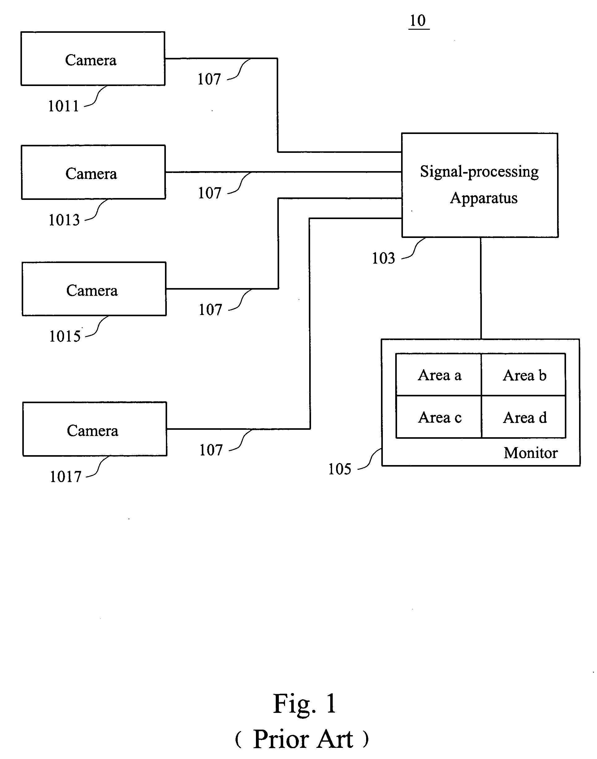
Besides, due to the feature of the special line 107, the addition or removal of another camera usually has to be involved in rearranging the wirings, and the wiring rearrangement is a very tedious job for the watcher.
If there are several watchers desiring to watch the monitored images at various places, the wiring rearrangement has to be involved, which is not only tedious but also expensive in cost.
However, among the current applications of using the web browser to read in the monitored images, most of them can only display one single, image, and does not support the display of multiple images and the function of dynamically adding images.
However, the user has to adjust the display of each browser respectively, and quite a lot of inconvenience is caused.
Overall, the conventional monitor systems mainly can monitor a fixed number of images, and are not allowed to display an arbitrary number of images.
However, those restrictions have restricted a watcher's actions with respect to various points of view, thus resulting in inconvenience of different levels of degree.

Method used


Image

  • Dynamic monitor system
  • Dynamic monitor system
  • Dynamic monitor system

Examples


Embodiment Construction

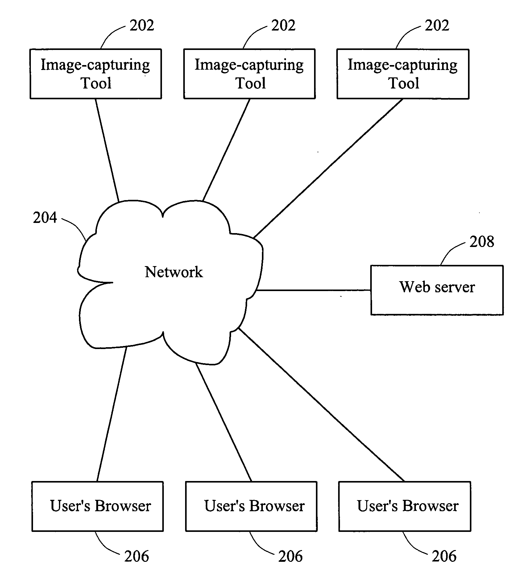
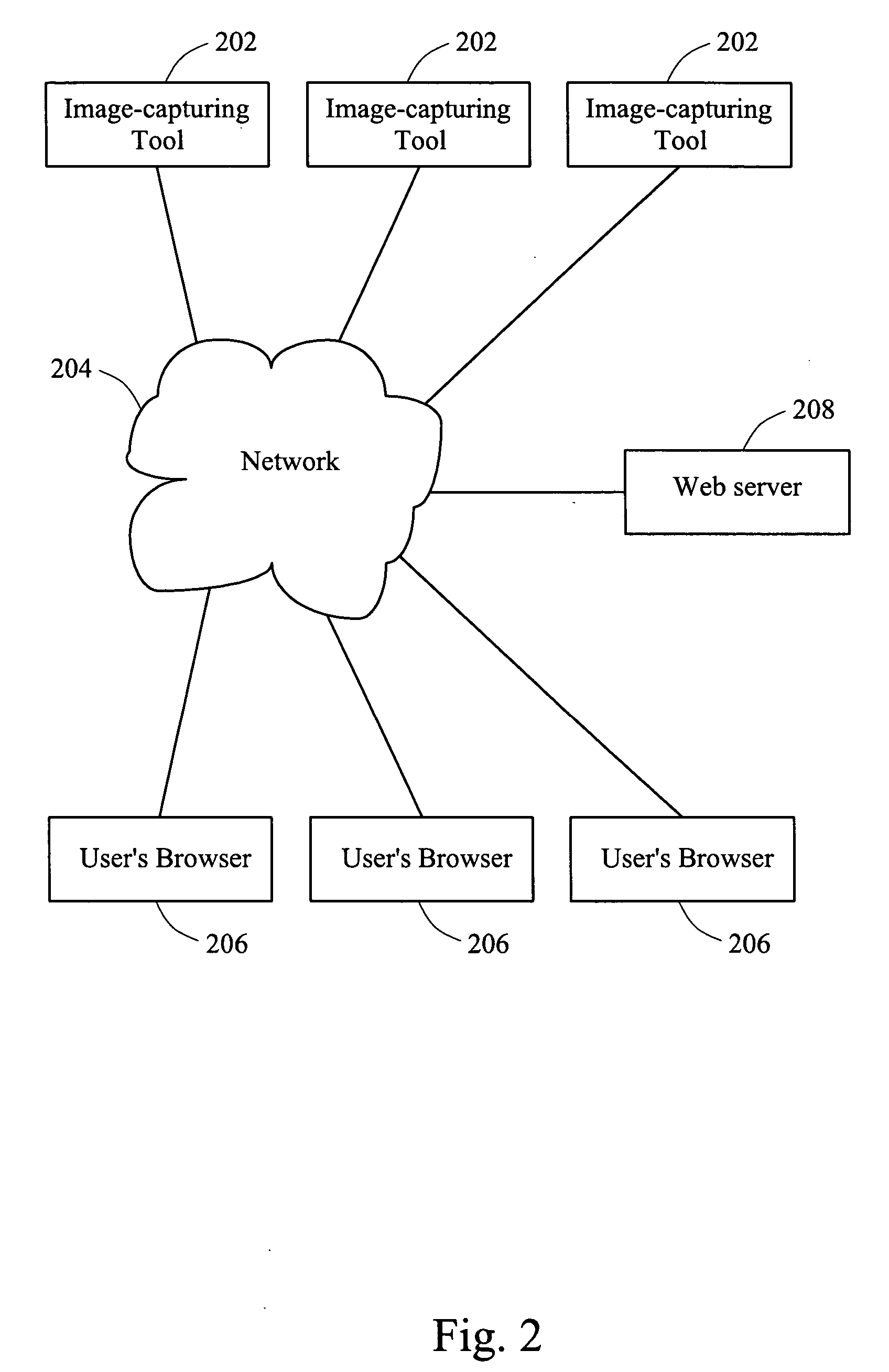
[0026] Referring to FIG. 2, FIG. 2 is a diagram showing the environmental allocation suitable for use in an embodiment of the present invention.

[0027] A plurality of image-capturing tools 202 are connected to a network 204, and the image-capturing tools 202 can be webcams having the function of web server, or any computers or electronic apparatus equipped with cameras. The image-capturing tools 202 are installed on each of the areas to be monitored. The network 204 herein can be any kind of local area networks, such as Ethernet, telecommunication network or Internet.

[0028] Meanwhile, what is also connected to the network 204 can be a browser 206 belonging to a user. The user may use any kind of computer or electronic apparatus that can execute the browser to establish a connection to the network and can retrieve network data via the browser. Besides, the network 204 is also connected to one or more web servers 208 for providing the contents of web page or web page programs. Under ...


PUM


Abstract

Monitor cameras are connected to a network and a user uses a browser to read in the images on these cameras via a network. Images captured by the cameras are displayed on the display area of the browser, and the user is allowed to add or delete any assigned video displays via an interface provided by a web page in the browser. While the user adds or deletes the video displays, the allocation of the display area of the browser is dynamically adjusted, so that the user can monitor a plurality of sites dynamically at the same time conveniently and flexibly.

Description

FIELD OF THE INVENTION [0001] The present invention relates to a dynamic monitor system, and more particularly to the remote monitor system that can access multiple images via a network. BACKGROUND OF THE INVENTION [0002] In order to control the situation of a bigger area under limited manpower, various monitor systems have been developed. These monitor systems are used in factories, parking lots, multi-story buildings and communities, etc. for performing the job of real time or taped security monitoring. [0003] Referring to FIG. 1, FIG. 1 is an allocation diagram of a conventional monitor system 10. The monitor system 10 has a plurality of cameras 1011, 1013, 1015 and 1017 used for capturing images on different monitored areas. After the cameras 1011, 1013, 1015 and 1017 are connected to a signal-processing apparatus 103 via a special line 107, the monitored images are displayed on several areas of a monitor 105, such as the monitored areas a, b, c and d shown in FIG. 1. [0004] The...

Claims


Application Information

Patent Timeline
Patent Type & Authority Applications(United States)
IPC IPC(8): H04N5/225H04N5/232H04N5/222
CPCH04N7/181H04N21/4314H04N21/4312
Inventor LIN, REHN-LIEH
Owner WINBOND ELECTRONICS CORP
Learn More