Skirted turbine blade

Active Publication Date: 2006-01-19
GENERAL ELECTRIC CO
View PDF7 Cites 6 Cited by
  • Summary
  • Abstract
  • Description
  • Claims
  • Application Information

AI Technical Summary

Benefits of technology

[0019] Accordingly, it is desired to provide an improved turbine blade having a twiste

Problems solved by technology

Since the rotor blades of the HPT are subject to the hottest temperatures of the combustion gases and rotate at high speed they are subject to considerable thermal and centrifugal stresses during operation.
Since the blade airfoil, platform, and dovetail are specifically configured for different purposes they experience different thermal and centrifugal loads during operation which must be suitably limited for ensuring a long useful life of the turbine stage.
Correspondingly, the supporting rotor disks must also be suitably configured for carrying the centrifugal loads from the row of rotor blades with limited stress for ensuring the long useful life

Method used


Image

  • Skirted turbine blade
  • Skirted turbine blade
  • Skirted turbine blade

Examples


Example

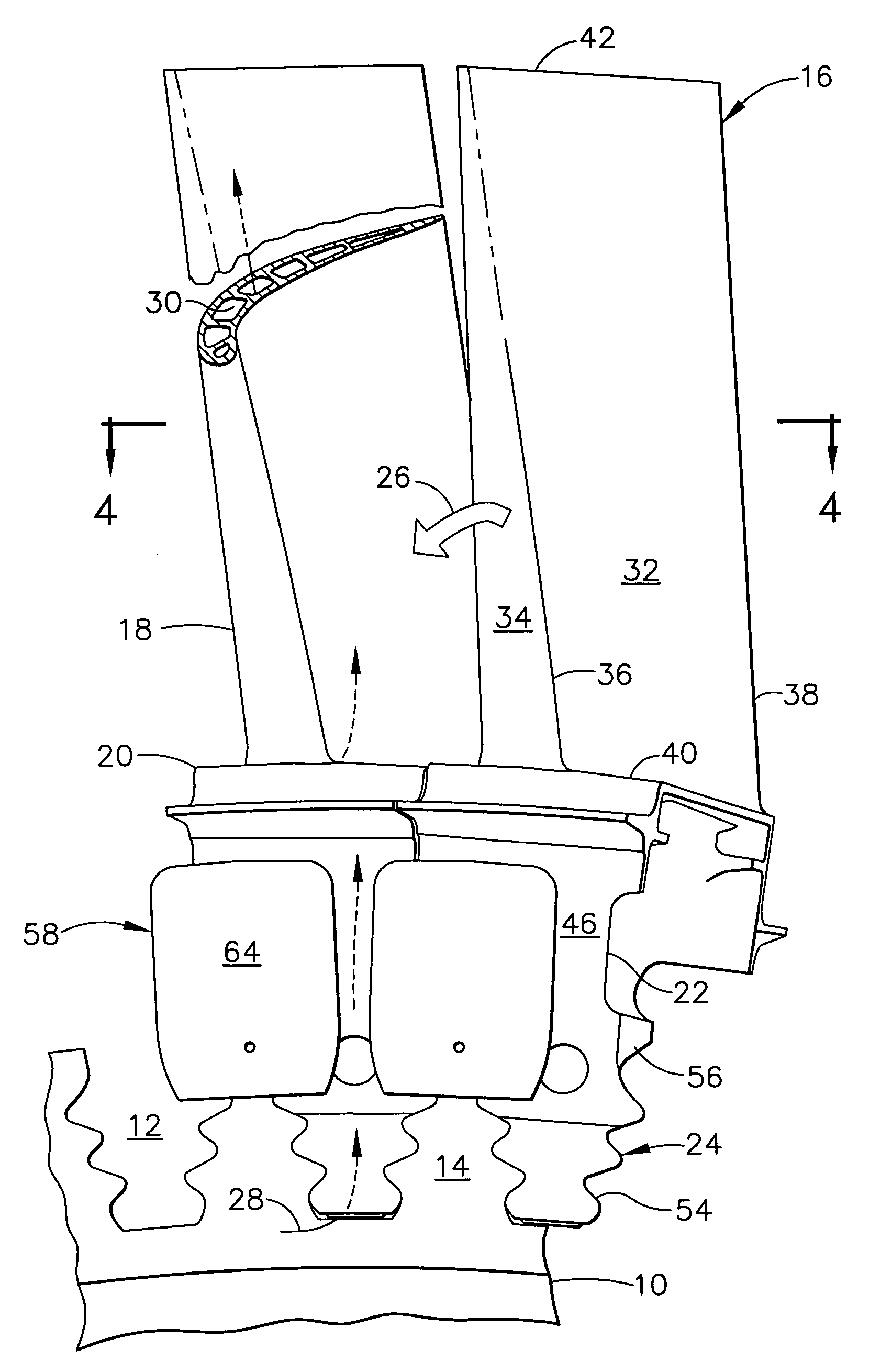
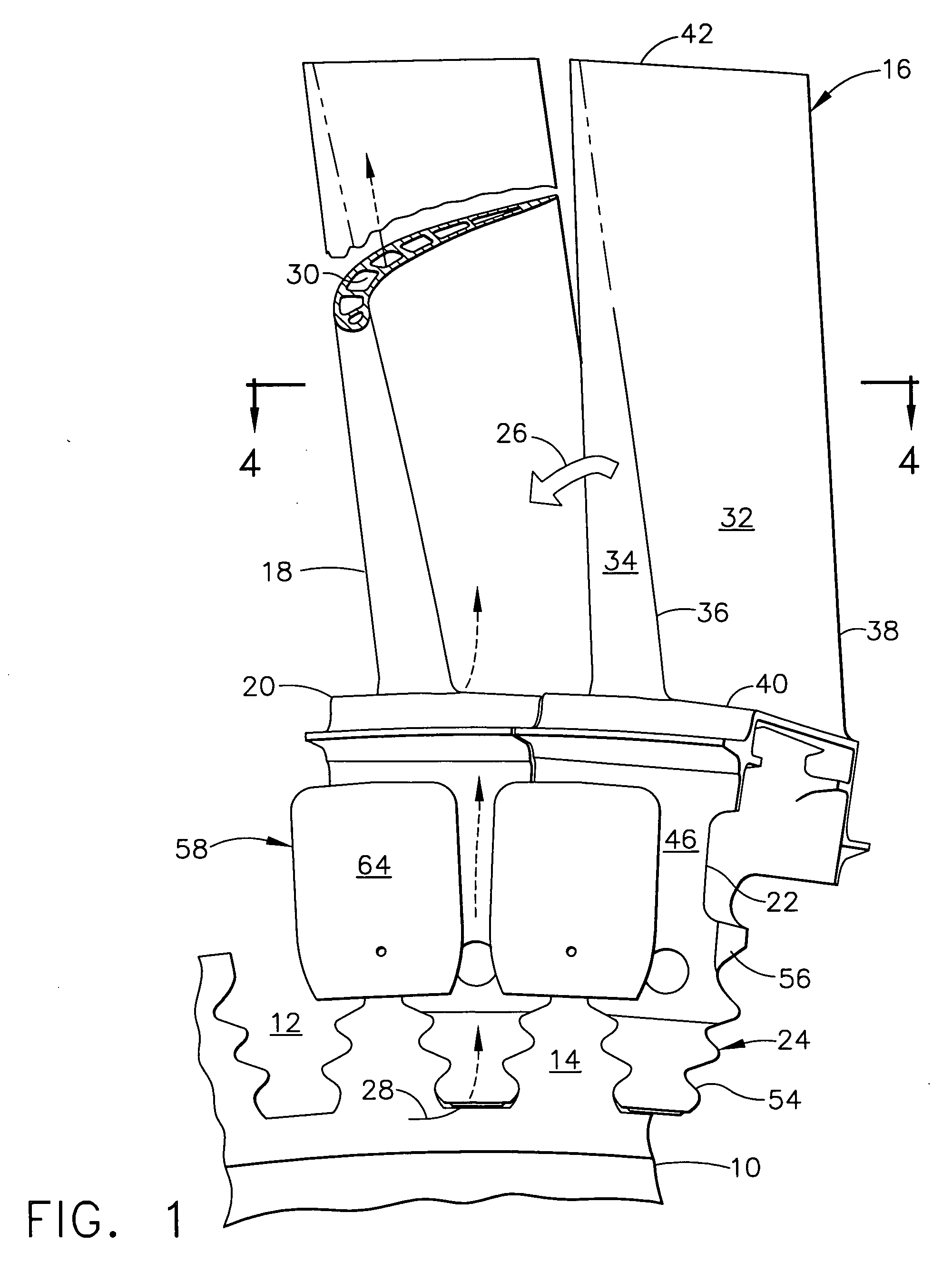
[0027]FIG. 1 illustrates a representative portion of a second stage turbine rotor of an HPT for an otherwise conventional gas turbine engine. The engine may be configured as a turbofan for powering an aircraft in flight, or for marine or industrial applications with an LPT driving an external drive shaft.

[0028] A turbine rotor disk 10, is shown in part and includes a row of axial dovetail slots 12 formed around the perimeter of the disk and defined by complementary disk posts 14.

[0029] A row of second stage turbine rotor blades 16 is mounted around the rotor disk in the corresponding dovetail slots 12. Each blade includes an airfoil 18, platform 20, shank 22, and multilobe dovetail 24 integrally joined together radially in turn in a unitary or one-piece casting.

[0030] During operation, hot combustion gases 26 are generated in a combustor (not shown) and are suitably channeled between the turbine airfoils 18 which extract energy therefrom for rotating the disk 10. The disk is suit...


PUM


Abstract

A turbine blade includes an airfoil, platform, shank, and dovetail. The shank includes opposite forward and aft faces corresponding with leading and trailing edges of the airfoil, and opposite first and second sides corresponding with pressure and suction sides of the airfoil. The shank further includes lugs extending outwardly from the two sides, with a first lug having an inverted skirt extending outwardly toward the platform to join the shank aft face. The skirt cooperates with a seal body when mounted in the engine for reducing inter-blade leakage.

Description

BACKGROUND OF THE INVENTION [0001] The present invention relates generally to gas turbine engines, and, more specifically, to turbine blades therein. [0002] In a gas turbine engine air is pressurized in a compressor and mixed with fuel in a combustor for generating hot combustion gases. Turbine stages extract energy from the combustion gases for powering the compressor and producing useful work. [0003] A high pressure turbine (HPT) immediately follows the combustor and includes one or more rows of turbine rotor blades which extract energy from the gases for powering the compressor. [0004] A multistage low pressure turbine (LPT) follows the HPT and includes additional rotor blades which also extract energy from the combustion gases for typically powering an upstream fan in a turbofan aircraft engine application. [0005] In yet another configuration, an intermediate pressure turbine (IPT) is disposed between the HPT and the LPT and includes additional turbine stages which also extract ...

Claims


Application Information

Patent Timeline
IPC IPC(8): B63H1/16
CPCY02T50/671F01D11/008Y02T50/60
Inventor ATHANS, ROBERT EDWARDHERMAN, WILLIAM CHARLESNORTON, BRIAN ALAN
Owner GENERAL ELECTRIC CO
Why Eureka
Try Eureka