Unlock instant, AI-driven research and patent intelligence for your innovation.

Power steering apparatus

a technology of power steering and steering shaft, which is applied in the direction of steering initiation, instruments, vessel construction, etc., can solve the problems of short flow rate of hydraulic fluid, user's feeling an obstruction against his steering, and deteriorating smooth steering force, so as to achieve smooth steering force change

Active Publication Date: 2006-01-19
JTEKT CORP
View PDF8 Cites 8 Cited by
  • Summary
  • Abstract
  • Description
  • Claims
  • Application Information

AI Technical Summary

Benefits of technology

[0012] The present invention has been made with the aim of solving the above problems, and it is an object thereof to provide a powe

Problems solved by technology

As a result, there is a problem that the flow rate of the hydraulic fluid runs short in such steering condition and the user feels an obstruction against his steering.
Although the shortage in the flow rate of the hydraulic fluid is solved by increasing the slope of rotational speed / steering speed so that high rotational speed is obtained even with low steering speed, there is a problem that the steering assistance force changes rapidly in such a method and the smoothness of the steering force deteriorates.

Method used


Image

  • Power steering apparatus
  • Power steering apparatus
  • Power steering apparatus

Examples


embodiment 1

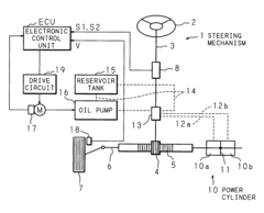
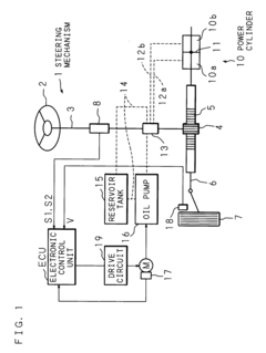
[0033]FIG. 1 is an explanatory view schematically showing the structure of a main part of Embodiment 1 of a power steering apparatus according to the present invention. This power steering apparatus is constructed to assist steering to be performed at a steering mechanism 1 of a vehicle, in which a steering shaft 3 is connected with a steering wheel 2. Attached to a front end of the steering shaft 3 is a pinion 4, which engages with a rack shaft 5 extending in the vehicle width direction. A front wheel tire 7 is attached to the rack shaft 5 via a tie rod 6.

[0034] The rack shaft 5 is also connected with a piston 11 of a power cylinder 10, which comprises a pair of cylinder chambers 10a and 10b formed of a piston 11. The cylinder chambers 10a and 10b are connected with an oil pressure regulating valve 13 respectively through oil feed passages 12a and 12b shown in broken lines.

[0035] The oil pressure regulating valve 13 is connected at the middle of an oil circuit 14 shown in broken ...

embodiment 2

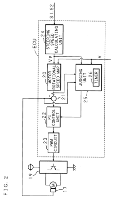
[0056]FIG. 5 is a block diagram showing an example of the structure of an electronic control unit, a drive circuit, an electric motor and a rotational speed sensor of Embodiment 2 of a power steering apparatus according to the present invention. In an electronic control unit ECU, a motor rotational speed map 20a, which has a map for defining the relation between the steering speed, the vehicle speed and the motor rotational speed as shown in FIG. 4, outputs indicated rotational speed (target rotational speed) to an electric motor M in accordance with a given steering speed signal Vθ and a given vehicle speed signal V and gives the indicated rotational speed to a deviation computing unit 21 and a judging unit 25a (judging means and holding means).

[0057] Rotational speed detected by a rotational speed sensor 17 of the electric motor M is given to the deviation computing unit 21, and the deviation computing unit 21 subtracts the rotational speed from the indicated rotational speed to ...


PUM


Abstract

A power steering apparatus according to the present invention is constructed to calculate a rate of change of steering speed detected by steering speed detecting means and judge whether the calculated rate of change is smaller than or equal to 0 or not, and reduce a gain of feedback control in comparison with a gain at the time of judgment when it is judged that the rate of change remains smaller than or equal to 0 for a predetermined time period and keep the reduced gain of feedback control until the deviation between target rotational speed and actual rotational speed of an electric motor becomes larger than 0.

Description

CROSS-REFERENCE TO RELATED APPLICATIONS [0001] This Nonprovisional application claims priority under 35 U.S.C. §119(a) on Patent Application No. 2004-163733 filed in Japan on Jun. 1, 2004, the entire contents of which are hereby incorporated by reference. BACKGROUND OF THE INVENTION [0002] 1. Field of the Invention [0003] The present invention relates to a power steering apparatus for controlling rotation of an electric motor using rotational speed based on vehicle speed and steering speed to assist steering with oil pressure generated by an oil pump which is driven by the electric motor. [0004] 2. Description of Related Art [0005] Recently, a hydraulic power steering apparatus for supplying a power cylinder connected to a steering mechanism of a vehicle with hydraulic fluid from an oil pump which is driven by an electric motor to generate steering assistance force from the power cylinder has become widely used. Such a power steering apparatus is designed to determine indicated rota...

Claims


Application Information

Patent Timeline
IPC IPC(8): B62D11/00B62D5/06B62D6/00B62D5/065B62D5/07B62D101/00B62D113/00B62D117/00B62D137/00
CPCB62D5/065B62D5/064
Inventor MITSUHARA, TAKASHI
Owner JTEKT CORP