Portable cutting tool

Inactive Publication Date: 2006-01-26
HITACHI KOKI CO LTD
View PDF9 Cites 7 Cited by
  • Summary
  • Abstract
  • Description
  • Claims
  • Application Information

AI Technical Summary

Benefits of technology

[0030] According to the invention, in the portable cutting tool including the cutting tool main body and the base, wherein an amount of the saw blade projected from the lower face of the base can be adjusted by pivoting the cutting tool main body relative to the base, the base and the tool main body are inclinably connected such that the saw blade can be projected from the vicinity of the intersection between the side face of the base and the lower face of the base, the parallelism between the saw blade and the side face of the base is made to be able to be adjusted and therefore, corner cutting operation can easily and accurately be carried out.
[0031] Further, according to the cutting tool of the invention, the support shaft constituting the fulcrum of the pivoting include

Problems solved by technology

When the pocket cutting operation is carried out by using the electric circular saw of the background art, in starting cutting operation, the front end portion 1a of the base 1 is pressed to the surface of the workpiece 30, the saw blade 3 is aligned to a position of a mark line drawn at the surface and thereafter, the workpiece 30 is cut, however, when the saw blade 3 is positioned while floating the rear end portion 1b of the base 1 in a state of rotating the saw blade 3, there poses a problem that the circular saw main body 2 becomes unstable.
Further, there also poses a problem that unless the circular saw main body 2 is firmly held, the saw blade 3 is shifted from the position of the mark line and it is difficult to cut the workpiec

Method used


Image

  • Portable cutting tool
  • Portable cutting tool
  • Portable cutting tool

Examples


Example

[0065] A first embodiment of an electric circular saw according to the invention will be described as follows. Further, constituent elements the same of those of FIG. 25 through FIG. 30 are attached with the same notations and a detailed explanation thereof will be omitted.

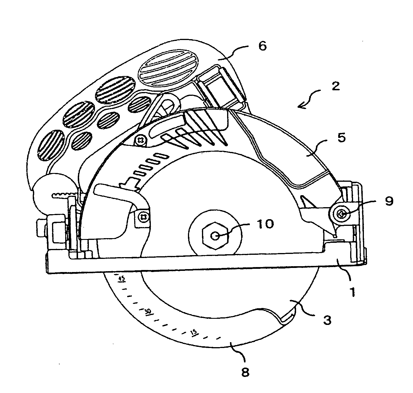
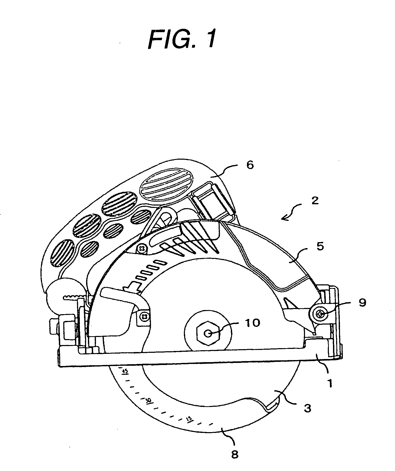
[0066] As shown in FIG. 1 through FIG. 6, an electric circular saw according to the embodiment is provided with a base 1 mounted on a workpiece 30 in cutting operation and a circular saw main body 2 attached with a saw blade 3 rotated by a motor (not illustrated).

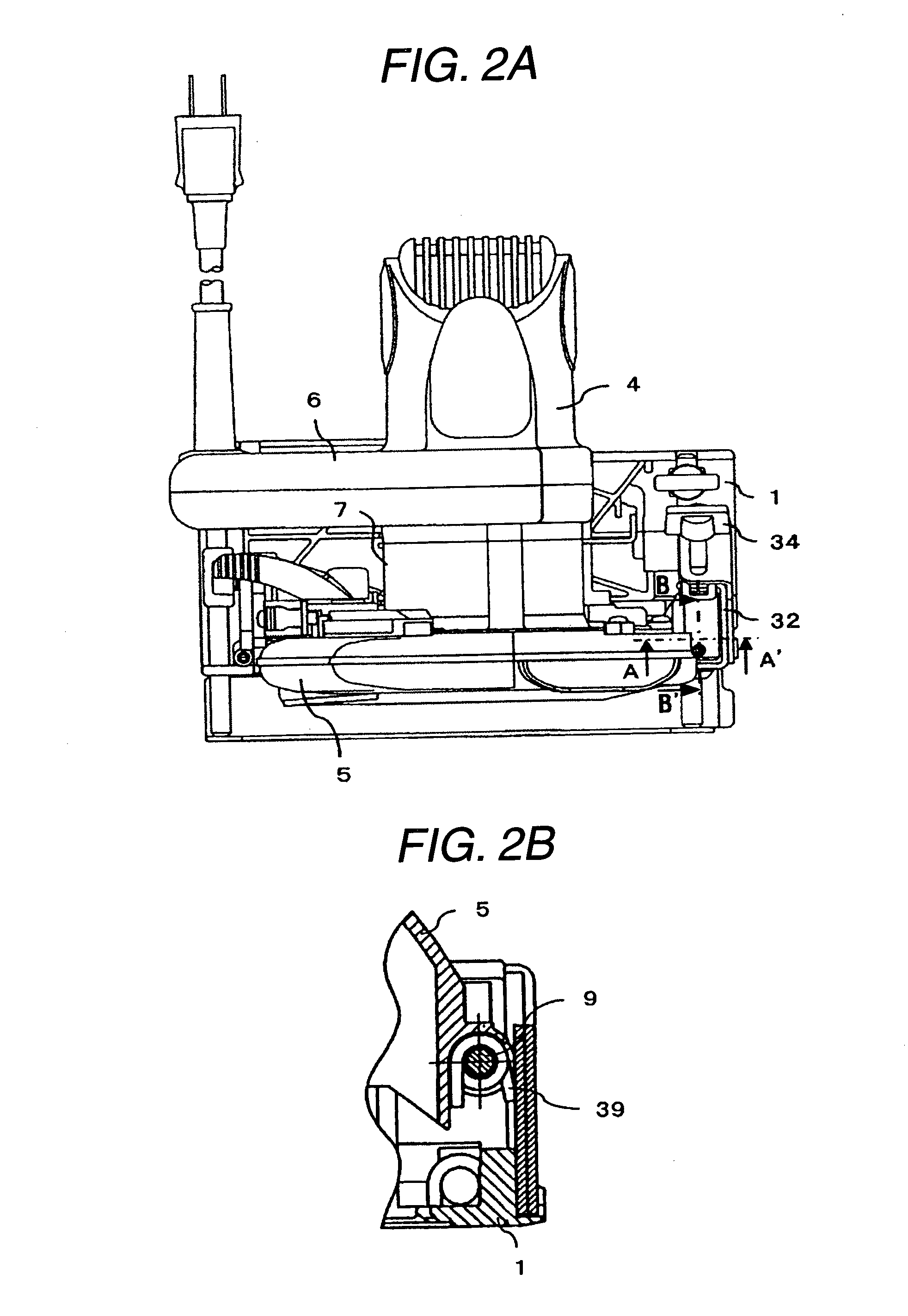
[0067] The motor is contained in a motor housing 8 (FIG. 2A) and the rotational drive force is transmitted to the saw blade 3 after the speed is reduced by a gear contained in a gear box 7. The circular saw main body 2 is constituted to be pivotable centering on a support shaft 9 relative to the base 1 and FIG. 1 shows a state in which the cut depth of the saw blade 3 projected from the lower face of the base 1 is the largest. Between the support shaft ...

Example

Second Embodiment

[0099]FIG. 18 and FIG. 19 show a second embodiment of a stopper mechanism of an electric circular saw according to the invention. Constituent elements in the drawings the same as those of FIGS. 13 through 17 are attached with the same notations and an explanation thereof will be omitted.

[0100] Although according to the first embodiment, the hook member 43 is fixed to the saw cover 5 and the stopper mechanism 53 is made to be able to fix to a desired position of the link member 40, according to the second embodiment, contrary thereto, a hook member 60 is made to be able to fix to a desired position of the link member 40 and the stopper mechanism 53 is fixed to the saw cover 5.

[0101] As shown in FIG. 18, a recess portion 60a is provided to the hook member 60 fixed to a desired position of the link member 40, when the saw cover 5 is moved down, a bottom portion of the stopper member 45 is engaged with the recess portion 60a and the cut depth is fixed at the position...

Example

Third Embodiment

[0103] Although according to both of the above-described embodiments 1 and 2, examples of fixing the link 40 to the base 1 are shown, according to a third embodiment, as shown in FIG. 20, the link 40 is made to be pivoted relative to the saw cover 5 and can be fixed to a desired position of the saw cover 5 by the lever 41. The second embodiment is constituted such that a bolt (not illustrated) fixed to the lever 41 and the saw cover 5 is made to be able to slide along the guide hole 42 of the link 40 and by pivoting the lever 41, a height position of the link 40 can be fixed to a desired position by pivoting the lever 41.

[0104] Further, as shown in FIG. 20, the second embodiment is constituted such that a claw portion 70 is provided at a lower end of the link 40 and when the circular saw main body 2 is pivoted by constituting a fulcrum by the support shaft 9, the claw portion 70 is engaged with a stopper mechanism 73 fixed to the base 1. As shown in FIG. 21, the st...


PUM


Abstract

A portable cutting tool includes a base and a tool main body which are inclinably connected such that a saw blade can be projected from a vicinity of an intersection between a side face of the base and a lower face of the base. A parallelism between the saw blade and the side face of the base is made to be able to be adjusted.

Description

BACKGROUND OF THE INVENTION [0001] 1. Field of the Invention [0002] The present invention relates to a portable cutting tool having a mechanism of adjusting a cutting depth of a saw blade, particularly relates to a portable cutting tool capable of fixing a cutting tool main body at a desired cutting depth position. [0003] A cutting tool according to the invention is suitable for so-to-speak pocket cutting operation in which a workpiece is not cut from an end portion thereof but the workpiece is slit from an upper portion thereof and the workpiece is cut while maintaining a cutting depth constant. Further, the cutting tool is suitable for so-to-speak corner cutting operation for cutting a floor member along a wall side for relining the floor member of a house. A description will be given as follows by taking an example of a portable electric circular saw for convenience of explanation. [0004] 2. Description of the Related Art [0005] An example of a portable electric circular saw of a...

Claims


Application Information

Patent Timeline
IPC IPC(8): B23D45/16
CPCB27B9/02
Inventor NIWA, KENJIIMAI, TERUO
Owner HITACHI KOKI CO LTD
Why Eureka
Try Eureka