Stator for electric rotating machine and method of manufacturing the same

Active Publication Date: 2011-04-28
DENSO CORP
View PDF8 Cites 22 Cited by
  • Summary
  • Abstract
  • Description
  • Claims
  • Application Information

AI Technical Summary

Benefits of technology

[0010]With the above method, since each of the planar electric wires is rolled through plastic deformation into the spiral or circular-arc shape, no spring back of the electric wires will occur after the rolling step. Consequently, in the subsequent step of forming the stator coil, it is possible to easily and accurately perform the operations of making relative axial movement between the rolled electric wires, thereby facilitating the assembling of the rolled electric wires. Further, after the step of forming the stator coil, it is possible to reliably prevent misalignment between the corresponding in-slot portions of the rolled electric wires from occurring, thereby reliably keeping the hollow cylindrical shape of the

Problems solved by technology

However, due to springback of the electric wires which are only elastically deformed during the rolling step, it may be easy for misalignment between the corresponding in-slot portions of the electric

Method used


Image

  • Stator for electric rotating machine and method of manufacturing the same
  • Stator for electric rotating machine and method of manufacturing the same
  • Stator for electric rotating machine and method of manufacturing the same

Examples


Example

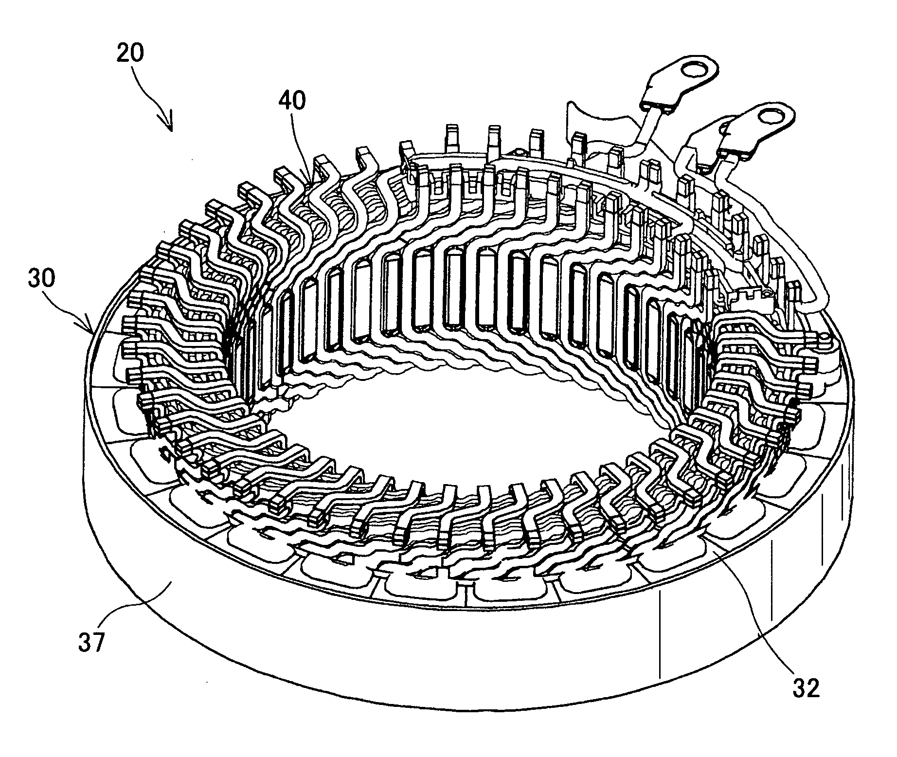
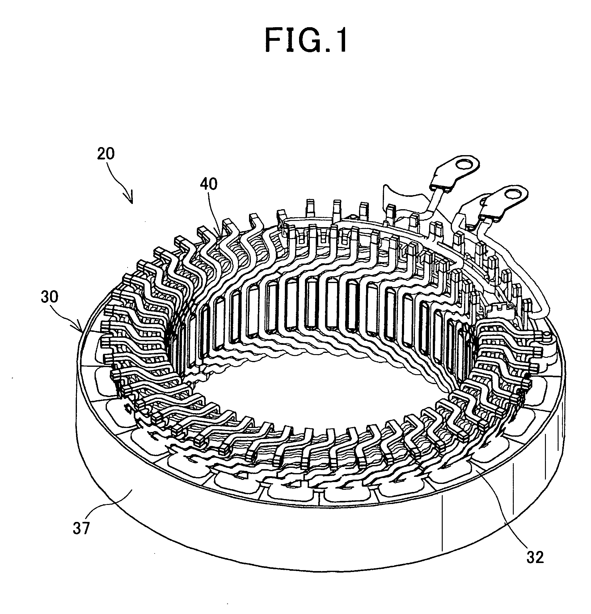
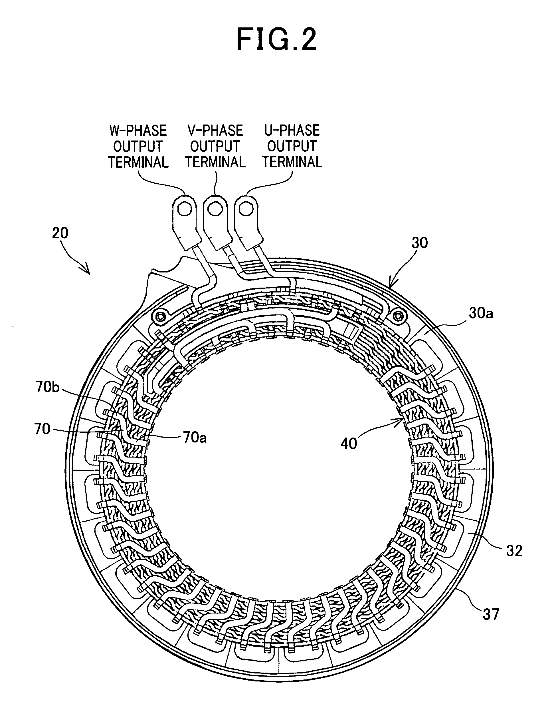
[0060]FIGS. 1-3 together show the overall configuration of a stator 20 according to an embodiment of the invention.

[0061]The stator 20 is designed for use in, for example, an electric rotating machine which is configured to function both as an electric motor and as an electric generator in a motor vehicle. The electric rotating machine further includes a rotor (not shown) that is rotatably disposed so as to be surrounded by the stator 20. The rotor includes a plurality of permanent magnets that form a plurality of magnetic poles on a radially outer periphery of the rotor to face a radially inner periphery of the stator. The polarities of the magnetic poles alternate between north and south in the circumferential direction of the rotor. In addition, in the present embodiment, the number of the magnetic poles formed in the rotor is equal to eight (i.e., four north poles and four south poles).

[0062]As shown in FIGS. 1-3, the stator 20 includes a hollow cylindrical stator core 30 and a ...


PUM

PropertyMeasurementUnit
Angleaaaaaaaaaa

Abstract

Disclosed is a method of manufacturing a stator for an electric rotating machine. The method includes the steps of: (1) forming a plurality of planar electric wires, each of the planar electric wires including a plurality of in-slot portions to be received in slots of a stator core and a plurality of turn portions to be located outside of the slots to connect the in-slot portions; (2) rolling each of the planar electric wires through plastic deformation into a spiral or circular-arc shape; (3) forming a hollow cylindrical stator coil by assembling the rolled electric wires through operations of making relative axial movement therebetween; and (4) assembling the stator core and the stator coil together to form the stator.

Description

CROSS-REFERENCE TO RELATED APPLICATIONS[0001]This application is based on and claims priority from Japanese Patent Applications No. 2009-244442 filed on Oct. 23, 2009 and No. 2010-232795 filed on Oct. 15, 2010, the contents of which are hereby incorporated by reference in their entireties into this application.BACKGROUND OF THE INVENTION[0002]1. Technical Field of the Invention[0003]The present invention relates to stators for electric rotating machines that are used in, for example, motor vehicles as electric motors and electric generators, and to methods of manufacturing the stators.[0004]2. Description of the Related Art[0005]Conventionally, there are known stators for electric rotating machines which include a hollow cylindrical stator core and a stator coil.[0006]The stator core has a plurality of slots that are formed in the radially inner surface of the stator core and spaced in the circumferential direction of the stator core. The stator coil is comprised of a plurality of e...

Claims


Application Information

Patent Timeline
IPC IPC(8): H02K3/12H05K13/00
CPCH02K3/28H02K15/0414H02K15/02Y10T29/49071Y10T29/49009Y10T29/49012Y10T29/49002H02K15/026
Inventor NAKAMURA, SHIGENOBU
Owner DENSO CORP
Why Eureka
Try Eureka