Moisture removal device

Inactive Publication Date: 2006-01-26
CHIANG KUO CHING
View PDF6 Cites 14 Cited by
  • Summary
  • Abstract
  • Description
  • Claims
  • Application Information

AI Technical Summary

Benefits of technology

[0003] A purpose of the invention is to provide a means for an object that allows for removal of moisture and condensation on the glass without the need for any external fan and allows for minimum reduction of visibility through the window due to moisture. The object includes a vehicle windshield, wind glass or a vehicle rearview mirror or glass door panel of a freezer or the glass portion of the freezer, wherein the transparent conductive pattern is attached at least partially one side such as the interior of

Problems solved by technology

Both of the ion beam an

Method used


Image

  • Moisture removal device
  • Moisture removal device
  • Moisture removal device

Examples


Example

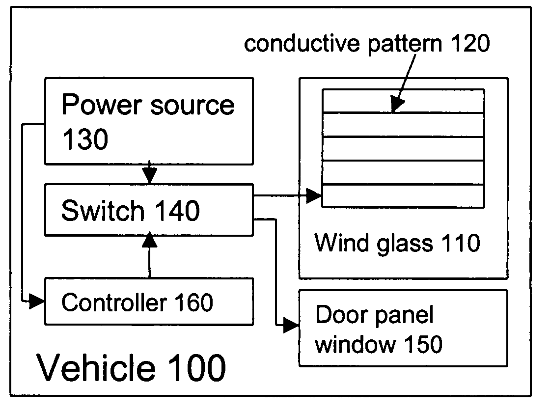
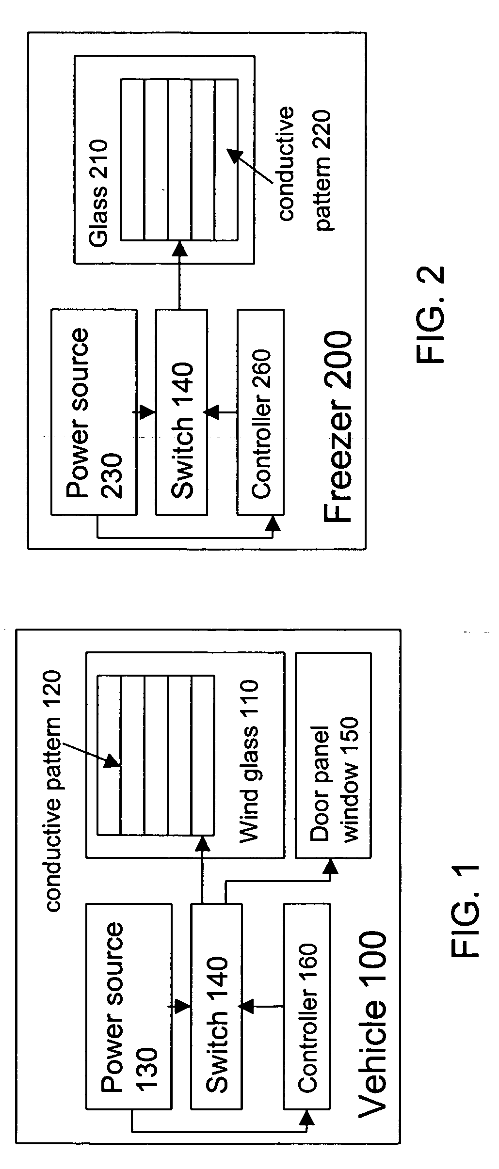
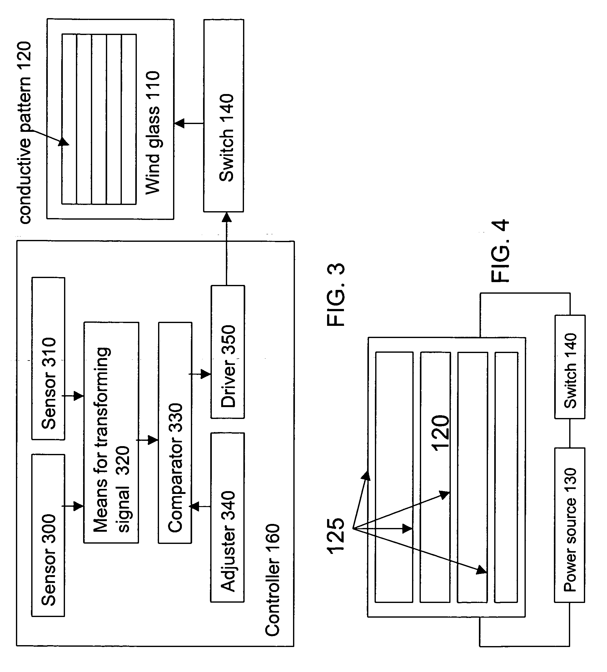
[0011] The present invention describes means for removing moisture on an object, for example window, glass or the like. See FIGS. 1, 2, and 3. The vehicle 100 has a rear windshield 110, door panel window 150 and a rearview mirror (not shown). The rear windshield 110 or the door panel window 150 has a conductive pattern or traces 120 located thereon. The pattern 120 may be a constructed by geometry figures, preferably, a plurality of strips connected together at both terminals. I should be noted, any configuration could be patterned to achieve the purpose. A power source 130 is coupled to the conductive pattern or traces 130 via a switch 140 to provide heat or power for removal the moisture on the object. The power could be provided by the battery of the vehicle for an example. In the example of the freezer 200 (refer to FIG. 2), electric power source 230 can be provided to the freezer, thereby conducting electricity to the conductive pattern or traces 220 on the glass 210 of the fre...


PUM


Abstract

The present invention discloses a moisture removal device includes a transparent conductive pattern attached partially on an object, wherein the material for the conductive pattern includes oxide containing metal or alloy, a power source is coupled to the conductive pattern for providing heat to the conductive pattern to remove fog or moisture on the object. An additional passive layer can be added to protect the conducting layer. Materials for this passivation layer are made, for instance, of oxide, or any other polymeric material, polymer, resin coating on the structure.

Description

FIELD OF THE INVENTION [0001] The present invention relates a means for removing moisture, and more particularly, a moisture removal device with a conductive transparent layer coated on an object to remove moisture on the object. BACKGROUND OF THE INVENTION [0002] Driving in rainy weather presents problems of visibility, it is because that the water droplets, moistures are deposited on the surface of the rear windshield or the reflective surfaces of external rear view mirrors. Thus, the vehicle wind glass needs a device for removing condensation from windows in vehicle windshield or mirror. The rear windshield or rearview mirrors are commonly located at suitable position to allow the driver to view traffic in the lane. The windows have a tendency of fogging to the accumulation of moisture. Water vapor will tend to condense on the inner pane of the outer view window. It can turn to frost in the winter. It is also happen on the glass of a door panel of a freezer for cold storage. If t...

Claims


Application Information

Patent Timeline
IPC IPC(8): H05B1/02F26B19/00
CPCF25D21/08H05B2203/013H05B3/84
Inventor CHIANG, KUO CHING
Owner CHIANG KUO CHING
Why Eureka
Try Eureka