
Feeding mechanism auto-adjusting to load for use in automatic high-security destruction of a mixed load, and other feeding systems

a technology of automatic high-security destruction and feeding mechanism, which is applied in the field of mechanized loadfeeding and movement of a load, can solve the problems of large-dimensioned (non-portable) machinery, material may travel non-identical feed paths, damage or at least “stall” or jam the shredder, etc., and achieves high-security destruction, reduces the number of different input openings and/or feed paths, and slows the advance

Active Publication Date: 2006-01-26
CASTRONOVO CHARLES A
View PDF13 Cites 98 Cited by
  • Summary
  • Abstract
  • Description
  • Claims
  • Application Information

AI Technical Summary

Benefits of technology

[0013] The present invention relating to feeding a non-uniform load was accomplished after the present inventor was the first to invent a processing station that, surprisingly, could perform high-security destruction of non-uniform material without stopping for manual adjustment of the destruction machinery and without a problem of the destruction mechanism jamming or the like. Namely, even if a single processing station can accomplish, without manual adjustment, high-security destruction of sheets of paper as well as boards or cassettes, a thicker load (for example) may heat-up the processing station so much that it could be desirable to slow the advance of such a thicker load to avoid, for example, generating a high temperature. When the present inventor was presented with that novel question of feeding a non-uniform load to a single high-security destruction motorized processing station, he invented novel feeding methods, systems, apparatuses, etc. in which the motorized processing station and feeding path are disposed in a relationship that is both separate from each other and non-manually controlled. Significantly, the present inventor has recognized that through separation of the feeding function from the processing function, advantages may be achieved. The present inventor has recognized the disadvantages of conventional shredders, in which the feed system is locked in rate (by gears or chains or a combination thereof) to the shredding system, and has inventively eliminated the need, in a paper shredder, for the feed system to be locked in rate to the shredding system.
[0014] The present invention reduces the number of different input openings and / or different feed paths needed in a machine when a non-uniform load is being fed toward a processing station. In a particularly preferred example, one processing station may accomplish high security destruction of a non-uniform load of to-be-destroyed material that arrives via a single feed path regardless of the type of material. For example, the present invention advantageously can be used to eliminate any need to feed paper sheets into one destruction machine but to feed plastic cards (such as SMART cards, credit cards, CD's DVD's, etc.) into another destruction machine. Also, the present invention advantageously can be used to eliminate the need to manually adjust or take special precautionary actions with certain destruction machines before feeding a different kind of to-be-destroyed material.

Problems solved by technology

It conventionally had been recognized that the operative cutting mechanisms in paper shredders were designed to accommodate a particular thickness of paper and that inputting too thick a stack of pages, for example, could damage or at least “stall” or jam the shredder.
Merely meeting the recent security requirements demanding yet smaller-sized residue has occupied the shredder industry, as most of the shredder industry seemingly has been unable to design products to satisfy the new high-security shredder requirements.
However, within the disintegrator machine the different materials may travel non-identical feed paths.
Disintegrators are heavy, large-dimensioned (non-portable) machinery.
Thus, the question of feeding a significantly non-uniform load of to-be-destroyed material had not been encountered in the area of high-security destruction.

Method used


Image

  • Feeding mechanism auto-adjusting to load for use in automatic high-security destruction of a mixed load, and other feeding systems
  • Feeding mechanism auto-adjusting to load for use in automatic high-security destruction of a mixed load, and other feeding systems
  • Feeding mechanism auto-adjusting to load for use in automatic high-security destruction of a mixed load, and other feeding systems

Examples


example 1

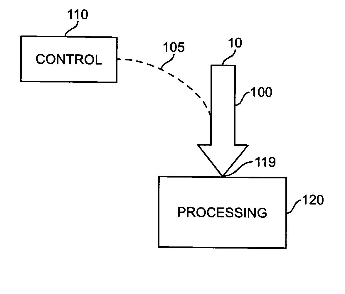
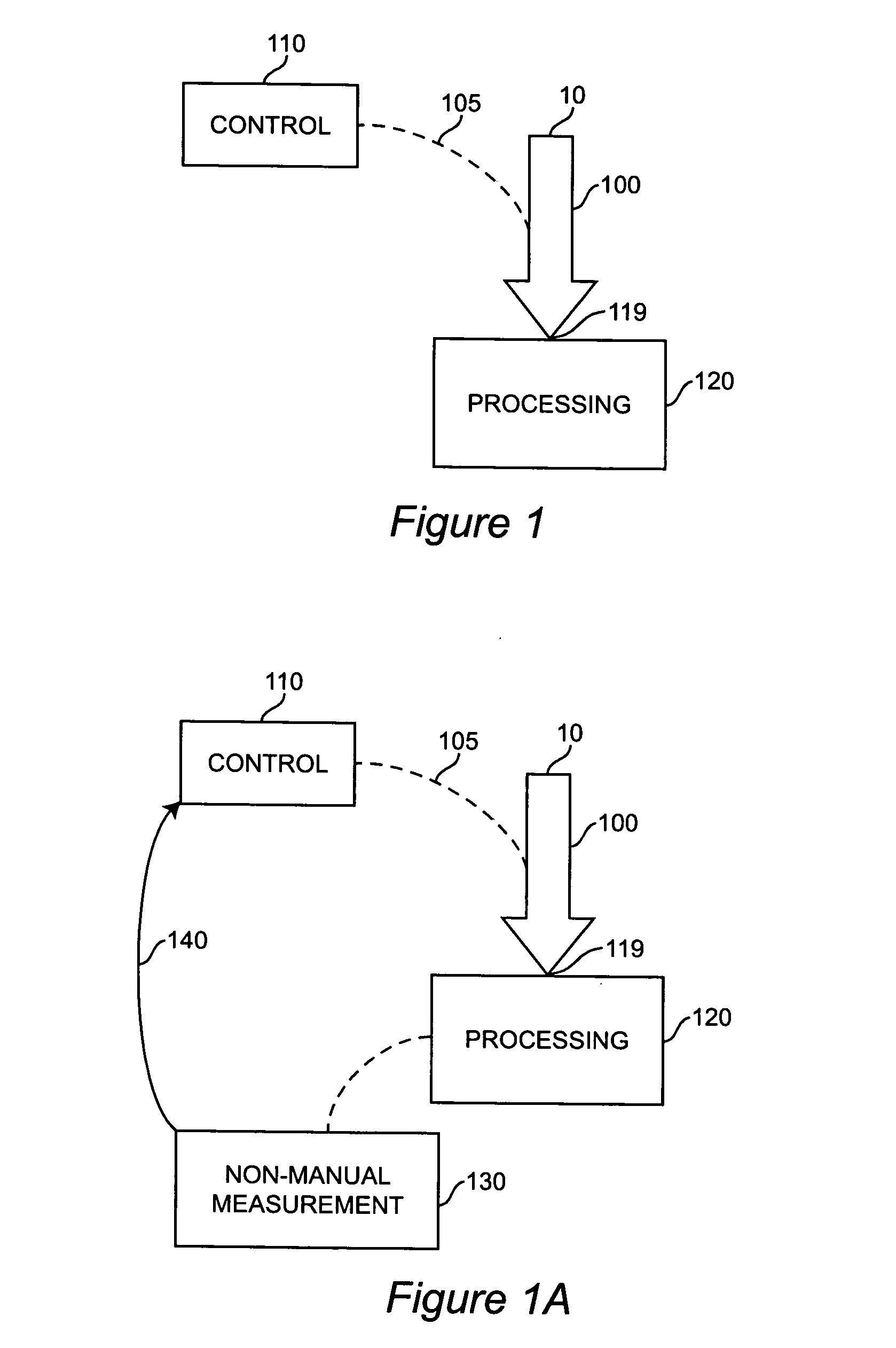
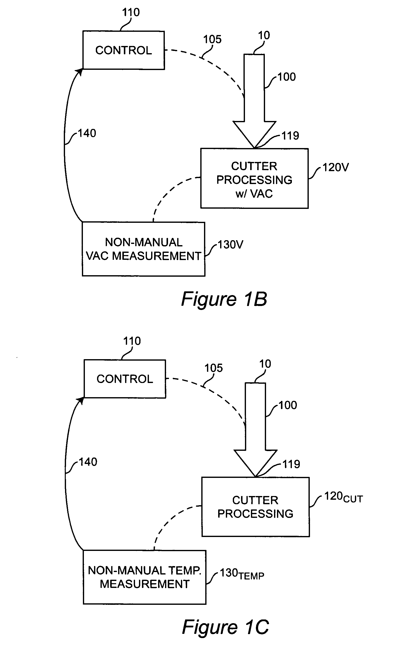
[0055] Referring to FIG. 1A, when the processing 120 comprises a motor-driven cutter (such as a rotating cutter), when the load (which may be a mixed load) is being fed towards the motor-driven cutter (such as a rotating cutter), the non-manual measurement 130 may be a measurement of current drawn by the cutter motor. In such a case, the current measurement is directly proportional to load.

example 2

[0056] When the processing 120 comprises a cutter, non-manual measurement 130 may comprise a crude, non-manual measurement of the load made before the load encounters the cutter. The feeding rate of the load (traveling on or in feed system 100) may be controlled 110 (such as slowed or increased) before the load encounters the cutter in processing 120. The system of this Example 2 may be used alone or in combination with a system of Example 1.

[0057] Referring to FIGS. 1, 1A, in a preferred embodiment, controlling 110 comprises a measurement (preferably a non-manual measurement) being made of the actual thickness of the load fed-in to feed system 100, and the feed is pre-slowed, as needed, in anticipation of the load's arrival 119 at the cutter.

example 2a

[0058] Pre-slowing as mentioned in Example 2 has been accomplished in one example by providing a spring-loaded, swinging vane that is pushed by load thickness. The vane actuates a switch, connected to the feed speed-control circuit that controls the feed path (such as feed path 100 in FIGS. 1 or 1A).


PUM


Abstract

A inventive feeding mechanism continuously feeds and continuously subjects to shredding, cutting, recycling, sorting, or other processing, a load consisting of a mixture of different-thickness materials, such as a mixture of paper, compact disks (CDs), cassette tapes, videotapes, etc. The auto-adjusting feeding mechanism is useable in high-security destruction, food processing, recycling, sorting, processing, and other applications.

Description

RELATED APPLICATION [0001] This claims benefit of U.S. provisional application Ser. No. 60 / 590,904 filed Jul. 26, 2004 titled “Feeding mechanism auto-adjusting to load, for use in automatic high-security destruction of a mixed load, and other feeding systems.”FIELD OF THE INVENTION [0002] The present invention generally relates to mechanized load-feeding and movement of a load. BACKGROUND [0003] It often is desired to feed a load (such as material to be destroyed, food to be shredded, etc.) towards a processing mechanism (such as a shredding mechanism, cutting mechanism, etc.). Conventionally, feeding mechanisms have been established for continuously moving materials within a certain range of dimensions towards the processing mechanism. For example, a load within a first range of thickness could be handled continuously, but the feeding mechanism would need to be stopped and manually adjusted before trying to feed a load of a second range of thickness. [0004] It has long been commonl...

Claims


Application Information

Patent Timeline
IPC IPC(8): B02C25/00
CPCB02C18/0007B02C18/2225B02C2018/0015B02C25/00B02C23/02
Inventor CASTRONOVO, CHARLES A.
Owner CASTRONOVO CHARLES A
Learn More