
Heat transfer system

a heat transfer system and heat transfer technology, applied in lighting and heating apparatus, chemical/physical/physico-chemical processes, chemical apparatus and processes, etc., can solve the problems of conductivity deterioration, thermal properties, increase in viscosity of heat medium, etc., to achieve delay in advance of freezing of heat medium, and suppressed advance of freezing

Inactive Publication Date: 2017-03-23
DENSO CORP
View PDF0 Cites 3 Cited by
  • Summary
  • Abstract
  • Description
  • Claims
  • Application Information

AI Technical Summary

Benefits of technology

The present patent aims to provide a heat transfer system that can prevent the heat medium from freezing and securing its antifreeze characteristic while avoiding a deterioration of its thermophysical properties and an increase of its viscosity. The system proposes the use of a solute that selectively approaches the solid-liquid interface of the heat medium and blocks its growth when its temperature falls below the base temperature, thus delaying the freezing point and preventing it from being advanced by a disturbance. This approach helps to maintain the heat medium's antifreeze characteristic and avoid its deterioration while securing its antifreeze characteristic. Additionally, the system prevents the solvent from approaching the solid-liquid interface, ensuring more effective suppression of the freezing process.

Problems solved by technology

However, thermophysical property such as a specific heat and a thermal conductivity deteriorates, and a viscosity of the heat medium increases when the concentration of ethylene glycol is increased.
The antifreeze characteristic thereby may not be secured sufficiently.

Method used


Image

  • Heat transfer system
  • Heat transfer system
  • Heat transfer system

Examples


first embodiment

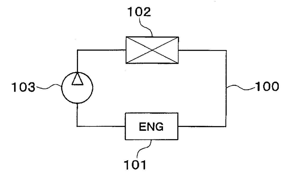
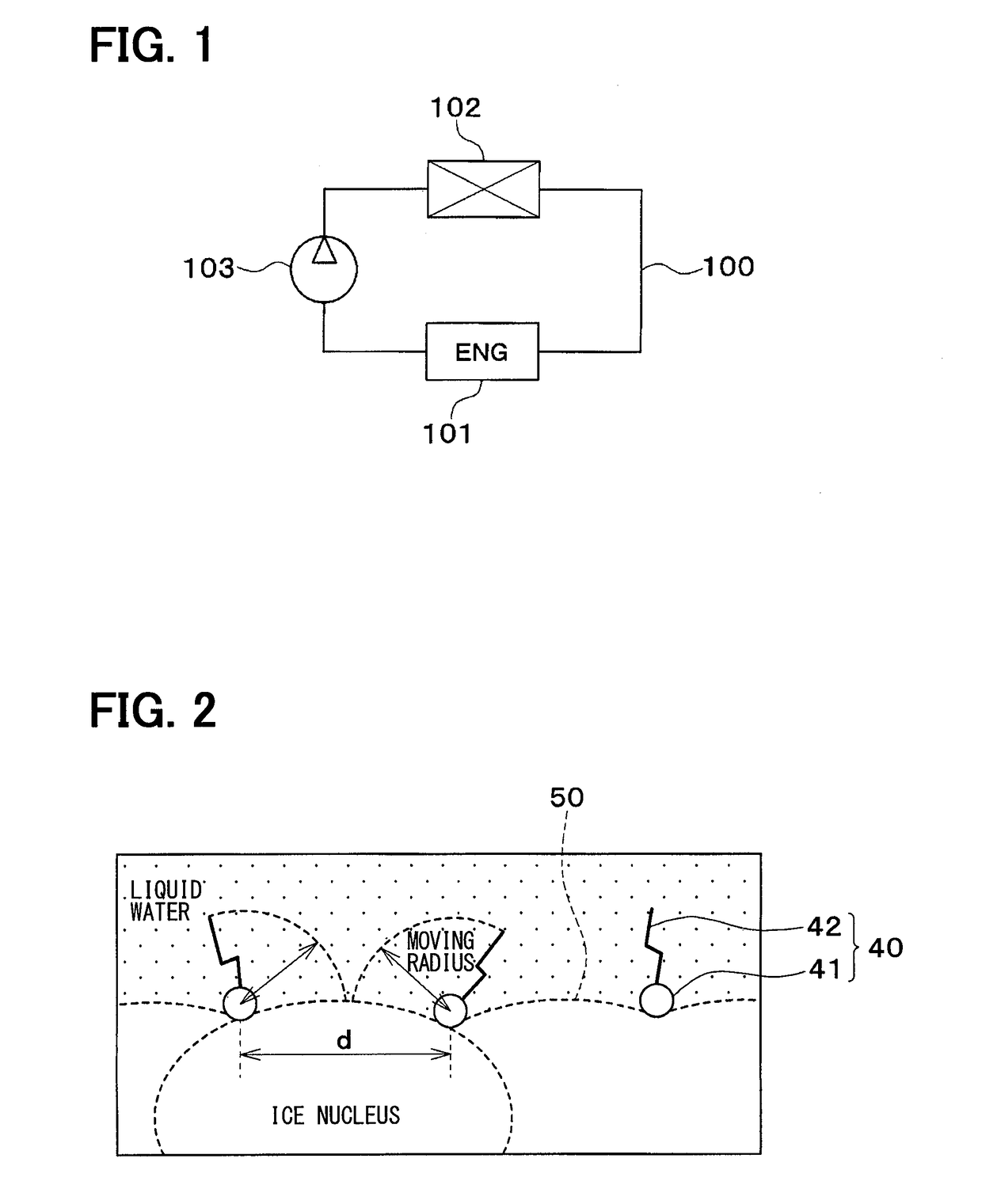
[0022]A first embodiment will be described hereafter referring to FIG. 1 through FIG. 5. A heat transfer system according to the present disclosure is used in a cooling system for an engine (i.e., an internal combustion engine) used as a driving source for moving a hybrid vehicle, in the present embodiment.

[0023]As shown in FIG. 1, the engine cooling system of the present embodiment is a system that cools cooling water for an engine 101 in a radiator 102. That is, the engine cooling system of the present embodiment is a system that transfers heat from the engine 101 to the radiator 102 through the cooling water that is a heat medium in a liquid state.

[0024]The engine 101 is a heat source that generates heat by an energy exchange. The radiator 102 is a heat exchanger that exchanges heat with an exhaust heat of the engine 101 and cools the cooling water having a high temperature by performing a heat exchange between the cooling water and outside air.

[0025]The engine 101 and the radiat...

second embodiment

[0048]A second embodiment will be described hereafter referring to FIG. 6. The second embodiment is different from the first embodiment in a point that the heat transfer system has two heat transfer circuits 1, 2 that are independent from each other.

[0049]As shown in FIG. 6, the heat transfer system of the present embodiment has the engine cooling system of the first embodiment and further has an intake air cooling system that cools an intake air for the engine. Specifically, the heat transfer system of the present embodiment has a first heat transfer circuit 1 that configures the engine cooling system and a second heat transfer circuit 2 that configures the intake air cooling system.

[0050]The first heat transfer circuit 1 is provided with the engine 101, the radiator 102, and the first pump 103 as described in the first embodiment. The first heat transfer circuit 1 is configured such that heat from the engine 101 is transferred to the radiator 102 through a first cooling water flow...


PUM

PropertyMeasurementUnit
freezing temperatureaaaaaaaaaa
temperatureaaaaaaaaaa

Abstract

A heat transfer system has a heat source that generates heat, a heat dissipator that dissipates heat, and a flow controller (hat controls a flow of a heat medium in a heat medium passage (n which the heat medium in a liquid state flows. The heat from the heat source is transferred to the heat dissipator through the heat medium. The heat medium is a solution that includes a solvent and at least one solute. The at least one solute is configured by a molecule. The molecule has (i) a first portion that selectively approaches a solid-liquid interface of the solvent when a temperature of the heat medium becomes lower than or equal to a predetermined base temperature and (ii) a second portion that is lyophobic and coupled with the first portion.

Description

CROSS REFERENCE TO RELATED APPLICATION[0001]This application is based on Japanese Patent Application No. 2014-106783 filed on May 23, 2014, the disclosure of which is incorporated herein by reference.TECHNICAL FIELD[0002]The present disclosure relates to a heat transfer system that transfers heat using a liquid heat medium.BACKGROUND ART[0003]A heat is generated in an energy exchange in an energy exchange system, for example, in a vehicle. Generally, such system is configured such that the heat generated in the energy exchange is transferred to be dissipated from a heat dissipator to outside the system. A liquid heat medium is used as the heat medium transferring the heat in most cases, and the liquid is required to be antifreeze liquid.[0004]Conventionally, a technique to secure an antifreeze characteristic is disclosed (e.g., refer to Patent Literature 1). According to the technique, a liquid provided by water to which ethylene glycol, as a freezing-point depressant, is added by 5...

Claims


Application Information

Patent Timeline
Patent Type & Authority Applications(United States)
IPC IPC(8): F28F23/02F28D15/00C09K5/20
CPCF28F23/02C09K5/20F28F2265/14F28D2021/0094F28D15/00B01J19/0013B01J2219/00054
Inventor FUSE, TAKUYAKANEKO, TAKASHIKAWAGUCHI, TOURU
Owner DENSO CORP
Learn More