
Spring clip and method of window installation

a technology of window installation and spring clip, which is applied in the field of construction business, can solve the problems of adding significantly to the labor cost and materials associated with window installation, and achieve the effects of reducing labor (time), slowing the advance of fire, and significantly increasing labor cost and materials

Inactive Publication Date: 2005-09-08
KOWNACKI CHARLES D
View PDF24 Cites 6 Cited by
  • Summary
  • Abstract
  • Description
  • Claims
  • Application Information

AI Technical Summary

Benefits of technology

[0003] SIPS construction involves manufacturing walls by sandwiching an insulating foam layer with a pair of oriented strand boards (OSBs) at the factory. The window openings are precisely positioned by computer controlled routers cutting away the OSB at the desired locations. Laborers using hot wire cutters or routers remove foam around the periphery of the opening to afford room for the framing lumber to be added around the perimeter. While the framing lumber performs three functions, it adds significantly to the labor cost and materials associated with window installation. These three functions are providing: 1) attachment points for the window, 2) structural integrity to the window opening, and 3) a fire barrier. The presence of framing lumber around the windows can slow the advance of the fire by up to 15 minutes as compared to the foam in the SIPS construction.
[0004] The spring clip of the present invention makes the inclusion of a nailing flange unnecessary, obviates the need for multiple installers and eliminates the need for installing framing lumber for standard size windows. The clips of the present invention replace other fastening clips which are screwed or nailed in place or other more time-consuming installation techniques. The spring clip is designed to penetrate portions of the insulating foam, have a tongue which is sandwiched between the OSB and the foam to ensure accurate positioning, and a spring finger which retracts to facilitate insertion of the window in the opening and then snaps back to engage a flange on the window unit to retain the window unit in the opening. An alternate fire barrier applied as a tape or spray coating will reduce the rate of fire propagation.

Problems solved by technology

While the framing lumber performs three functions, it adds significantly to the labor cost and materials associated with window installation.

Method used


Image

  • Spring clip and method of window installation
  • Spring clip and method of window installation
  • Spring clip and method of window installation

Examples


Embodiment Construction

)

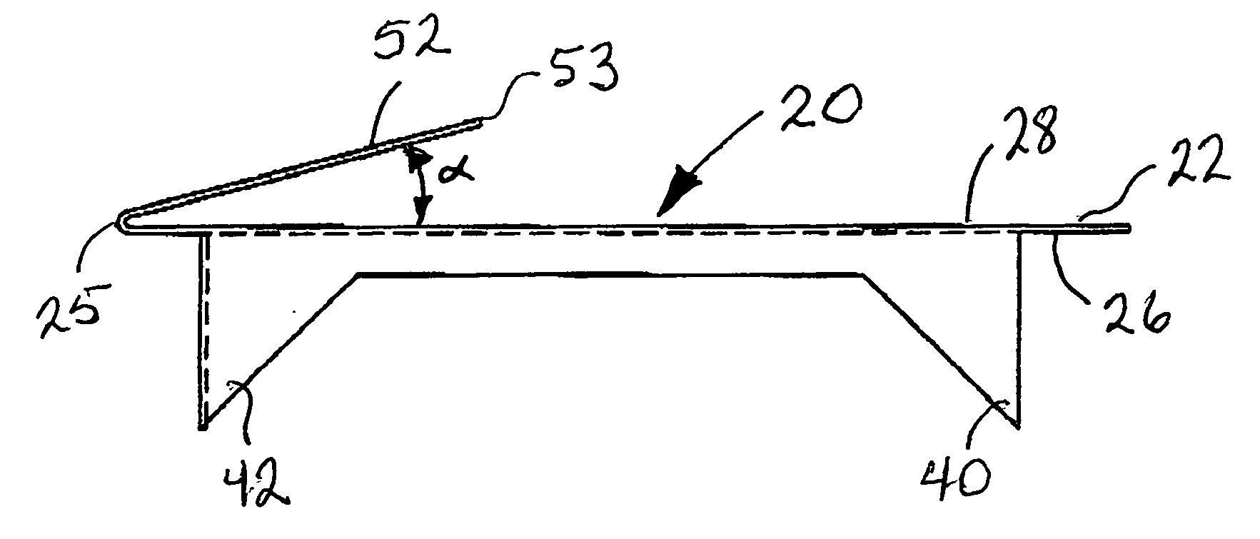
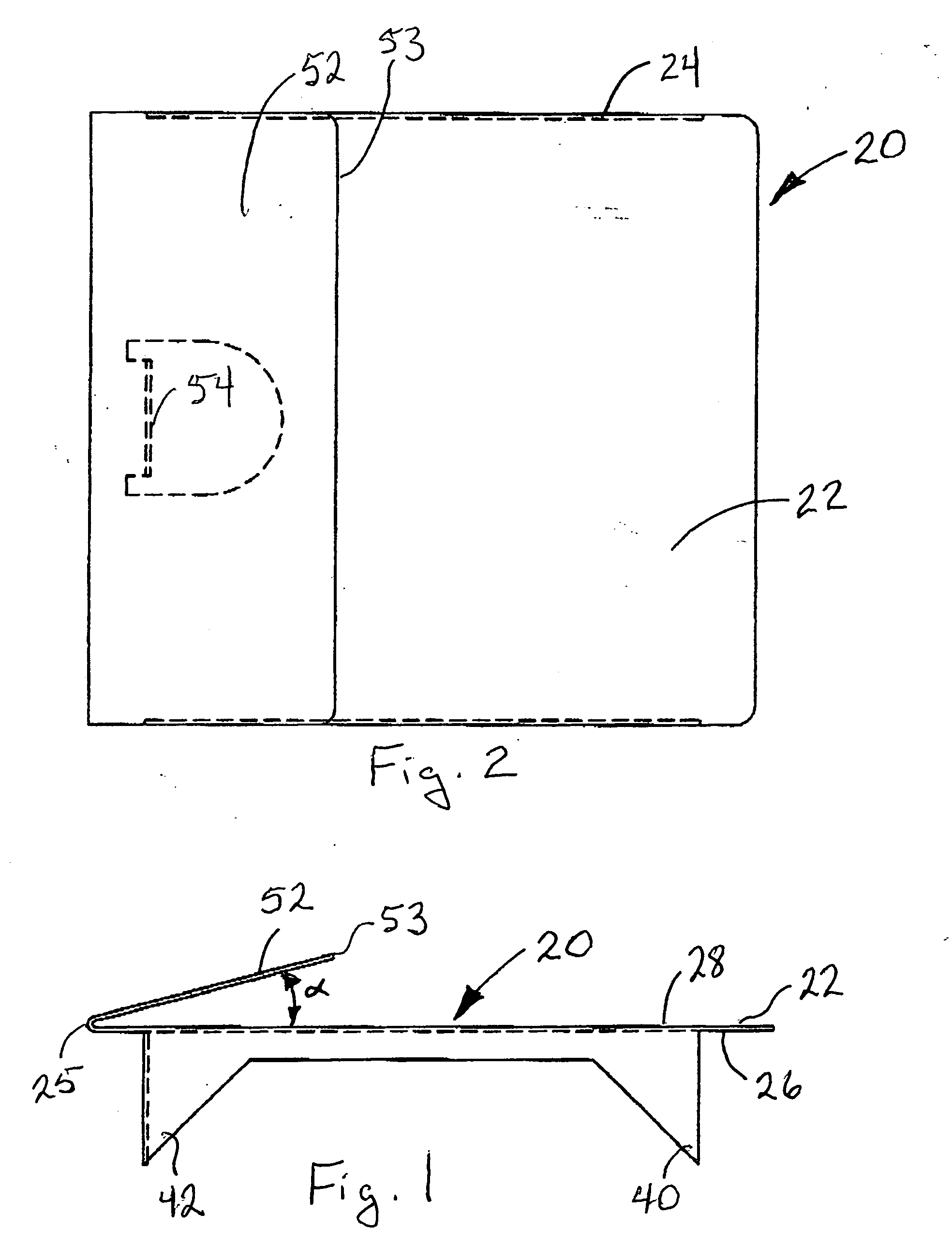
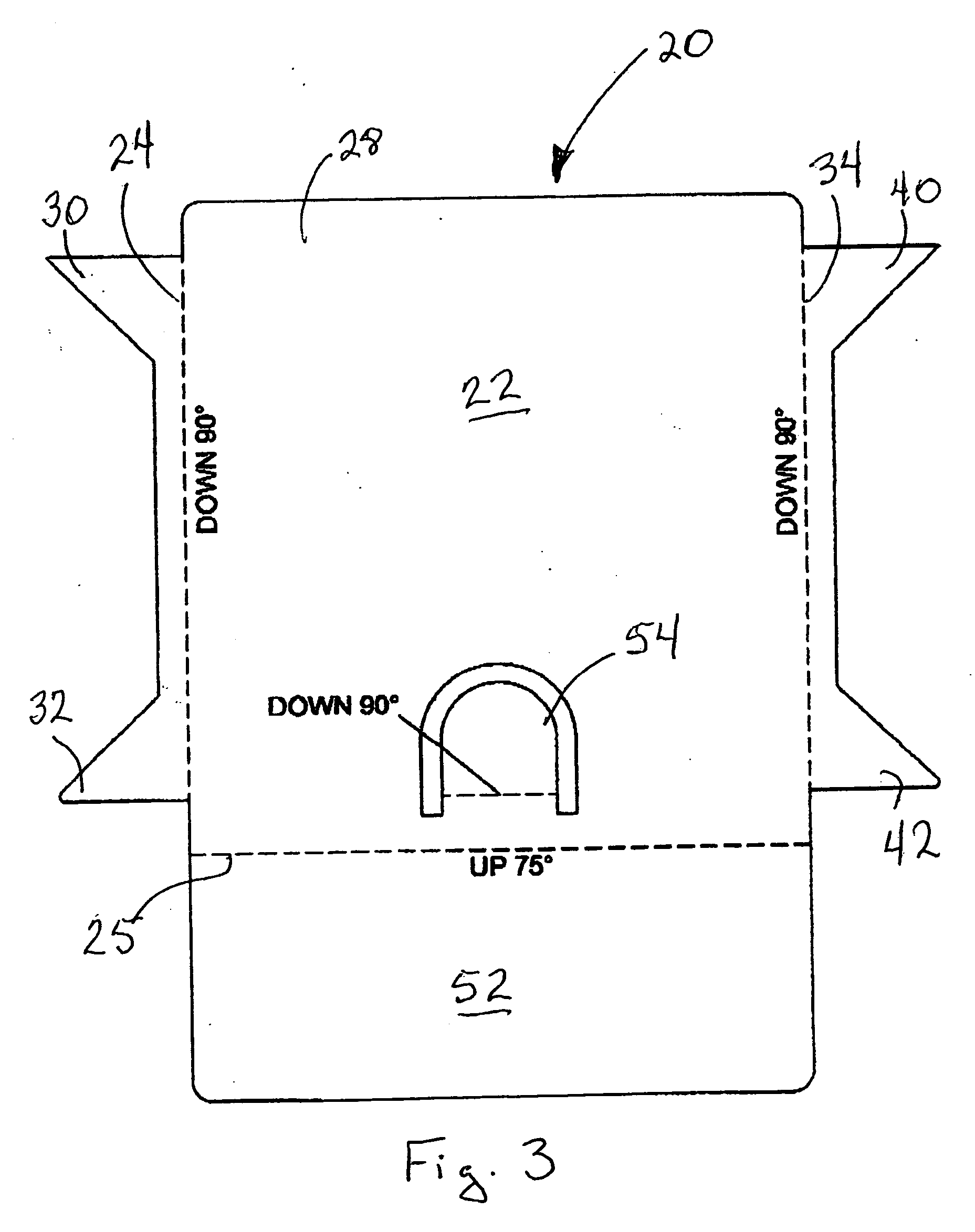
[0017] A first preferred embodiment of the spring clip of the present invention is shown in FIGS. 1-3 generally at 20. Spring clip 20 comprises a first planar surface 22 with a first upper edge portion 24 extending outwardly at a first angle to and projecting from the first planar surface 22 on a first side 26 thereof. Planar surface 22 has a second opposite side 28. First upper edge portion 24 has first and second integral, self-penetrating attachment means in the form of tangs 30, 32, respectively (FIG. 3), formed thereon. Second lower edge portion 34 extends outwardly at a second angle to and projecting from the first planar surface 22. Second lower edge portion 34 has third and fourth integral, self-penetrating attachment means, or tangs, 40, 42, respectively, formed thereon. The first and second angles are preferably, right angles or substantially right angles. A second planar surface 52 is attached to the first planar surface 22 along at least a portion of a length of a first...


PUM


Abstract

A spring clip having integral, self-penetrating attachment tangs and an orientation tab can be manually installed in a window opening formed by a foam core sandwiched by a pair of OSBs. A first planar surface has a second planar surface attached along one lateral edge thereof and oriented at an angle in the range between 60° and 85°. This spring finger deflects out of the way permitting the window's insertion, snapping back to engage a vertically extending flange on the window to retain it in the opening. A modified spring clip for use with solid wood headers and sills utilized with multi-unit windows is also disclosed.

Description

BACKGROUND AND SUMMARY OF THE INVENTION [0001] The present invention is directed to the construction business. More particularly, the present invention is directed to a spring clip to facilitate window installation and the associated method of installation. [0002] More specifically, the present invention is directed to a spring clip which has been specifically designed to decrease the amount of labor (time) needed to install a typical window in a standard framed home or a house built using a structural, insulated panel system (SIPS). Typically, a vinyl or wood window is manufactured with a nailing flange extending around the perimeter of the window. Window installation will usually require at least two installers, especially for windows being installed on the second (or higher) floor. Squaring and centering of the window is usually performed by the second installer while the first supports its weight, then secures it in the opening. [0003] SIPS construction involves manufacturing wa...

Claims


Application Information

Patent Timeline
Patent Type & Authority Applications(United States)
IPC IPC(8): E04C5/00
CPCY10T403/7096E06B1/6053F16B2200/67
Inventor KOWNACKI, CHARLES D.
Owner KOWNACKI CHARLES D
Learn More