Vibration damping control device for vehicle

a technology vehicle, which is applied in the direction of electric control, machines/engines, instruments, etc., can solve the problems of increasing the amount and frequency of operation of vibration damping control, the inability to simply manage such change of characteristic, and the degree of advance of wear or thermal deformation of the throttle valve movable parts

Inactive Publication Date: 2015-12-01
TOYOTA JIDOSHA KK
View PDF15 Cites 1 Cited by
  • Summary
  • Abstract
  • Description
  • Claims
  • Application Information

AI Technical Summary

Benefits of technology

[0006]The invention provides a vibration damping control device that uses driving power control equipped for a vehicle. More specifically, the invention provides a device that is able to manage a change of characteristic, such as a wear state of a throttle valve movable portion, so that the change of characteristic, such as wear of the throttle valve movable portion, does not exceed an allowable limit before the vehicle reaches the end of the service life.
[0008]With the above configuration, the magnitude of the compensating component is varied on the basis of the change of characteristic (for example, wear state quantity) of the movable portion of the throttle valve of the engine. By so doing, it is possible to regulate the operation amount of the throttle valve, so it is possible to manage the change of characteristic of the throttle valve so that the change of characteristic (for example, wear) of the throttle valve movable portion does not excessively advance or does not exceed an allowable limit before the vehicle reaches the end of the service life. Specifically, the compensating component regulating unit may be configured to reduce the magnitude of the compensating component of vibration damping control on the basis of the change of characteristic (for example, wear state quantity), more specifically, in association with an increase in the change of characteristic to thereby suppress fluctuations of the throttle opening degree corresponding to the magnitude of the compensating component as the change of characteristic advances. In addition, the compensating component regulating unit may forcibly set the magnitude of the compensating component of vibration damping control to 0 or stop the control when the change of characteristic (wear state quantity) has reached a predetermined threshold. In any case, operation of the throttle valve movable portion is limited in association with suppression of fluctuations of the throttle opening degree, so it is possible to delay the advance of the change of characteristic, such as wear, of the movable portion or to prevent further advance of the change of characteristic, such as wear. Thus, the throttle valve movable portion is protected so that the change of characteristic of the throttle valve movable portion does not excessively advance before the vehicle reaches the end of the service life. Note that the magnitude of the compensating component may be regulated by the compensating component regulating unit in such a manner that a control gain of the compensating component is varied. In this case, when the control is stopped, the control gain is set to 0.
[0019]Note that in the above described series of devices according to the aspects of the invention, for the purpose of managing the change of characteristic of the throttle valve, such as the degree of advance of wear of the throttle valve movable portion, it is desirable that a user, manager, mechanic, or the like, of the vehicle can check the change of characteristic or wear state quantity of the throttle valve or information as to whether the change of characteristic or wear state quantity exceeds a predetermined threshold. Thus, a further aspect of the invention provides a vibration damping control device that includes a device that provides information about a change of characteristic of a movable portion of a throttle valve of an engine of a vehicle or a wear state quantity information providing unit that provides information about a wear state quantity of a movable portion of a throttle valve of an engine, wherein the vibration damping control uses the information to determine the magnitude of a compensating component of driving power. With the above configuration, the change of characteristic or wear state quantity of the throttle valve may be referred to by a user, manager, mechanic, or the like, of the vehicle, so it is advantageously easily determine whether to perform repair, replacement, or the like, of the throttle valve without directly observing the movable portion, or the like, of the throttle valve or actually measuring the wear amount.
[0022]In addition, another aspect of the invention relates to a control method for a vehicle, which controls an opening degree of a throttle valve so as to suppress a vibration component input from a road surface. The method includes: calculating a wear state quantity of a movable portion of the throttle valve; and reducing a variation of the opening degree of the throttle valve when the wear state quantity is higher than a predetermined value.
[0024]In addition, another aspect of the invention relates to a vibration damping control method for a vehicle, which executes vibration damping control in which driving power of the vehicle is controlled to suppress pitch vibration or bounce vibration of the vehicle. The method includes: estimating a wear portion of a movable portion of a throttle valve of an engine; and reducing the magnitude of a compensating component that compensates a wheel torque for the vibration damping control when a required opening degree of the throttle valve corresponds to the wear portion.
[0027]As is already described above, vibration damping control using driving power control, described in the aspects of the invention, requires frequent variations of power as compared with existing driving power control, so, when the vibration damping control is applied to a gasoline engine vehicle, the change of characteristic, such as wear and thermal deformation, of the throttle valve movable portion tends to easily advance; however, this fact is not pointed out until the present time, and a technique for managing the change of characteristic, such as wear and thermal deformation, or handling easy advance of the change of characteristic has not been suggested. According to the above aspects of the invention, it is impossible to stop the change of characteristic, such as wear and thermal deformation, during vibration damping control; however, the change of characteristic of the throttle valve, such as the degree of advance of wear of the throttle valve movable portion, is appropriately managed to thereby make it possible to reduce operation of vibration damping control, stop the control or use alternative means when the change of characteristic, such as wear and thermal deformation, has advanced to some degree to thereby make it possible to suppress further advance of the change of characteristic, such as wear and thermal deformation, so it is possible to ensure the safety of operation of the throttle valve movable portion through normal driving operation of the vehicle until the end of the service life of the vehicle. In addition, some aspects of the invention provide a configuration that identifies a wear state of a throttle valve movable portion during running of a vehicle. The above configuration may be advantageously used to manage the wear state of the throttle valve movable portion.

Problems solved by technology

For example, on a bad road, as the vibration of the vehicle body increases, the amount and frequency of operation of vibration damping control increase.
It is not appropriate to simply manage such change of characteristic on the basis of the travel distance or service age of the vehicle.
However, as is already described above, the degree of advance of wear or thermal deformation of the throttle valve movable portions depends on the condition of a running road.

Method used


Image

  • Vibration damping control device for vehicle
  • Vibration damping control device for vehicle
  • Vibration damping control device for vehicle

Examples


Embodiment Construction

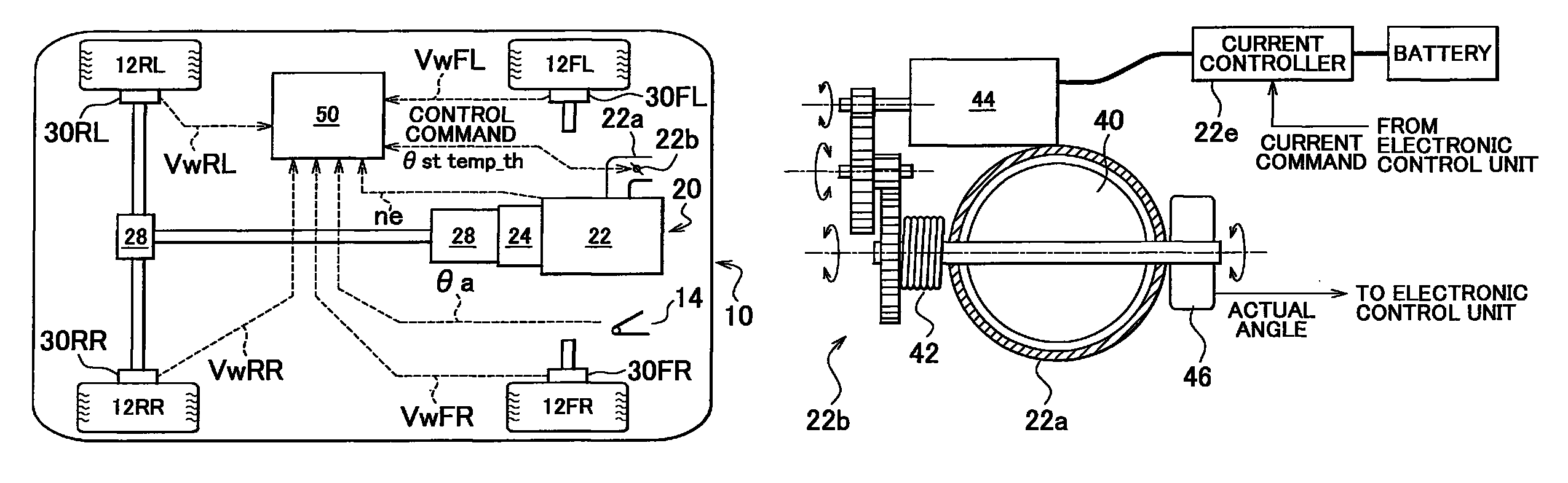
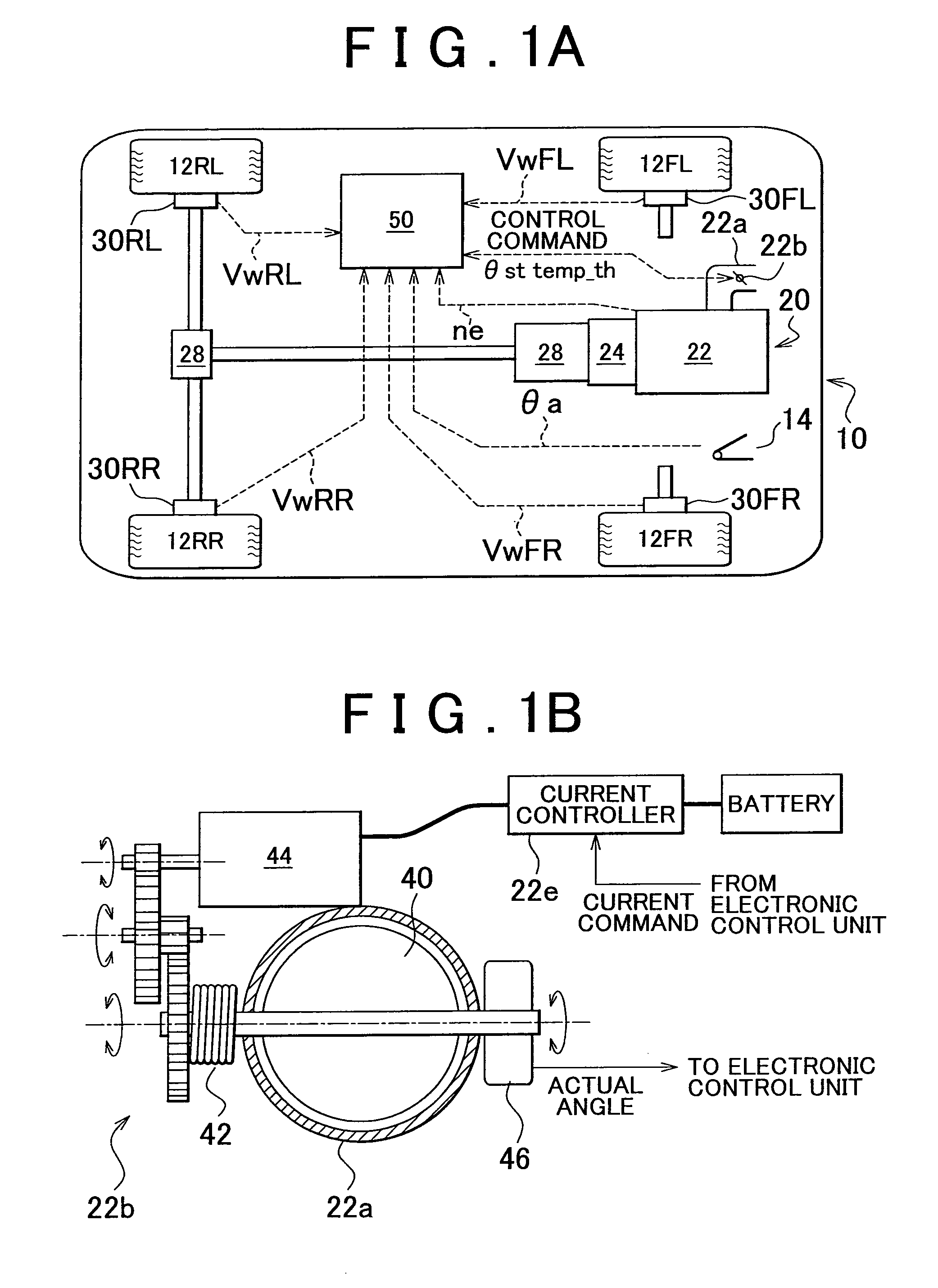
[0046]FIG. 1A schematically shows a vehicle, such as an automobile, equipped with a driving control device that executes vibration damping control according to an embodiment of the invention. In the drawing, the vehicle 10 includes a front left wheel 12FL, a front right wheel 12FR, a rear left wheel 12RL and a rear right wheel 12RR, and includes a driving device 20 that generates driving force or driving torque in accordance with driver's operation of an accelerator pedal 14 in a normal mode. In the example shown in the drawing, the driving device 20 is configured to transmit driving torque or rotational driving force from an engine 22 to the rear wheels 12RL and 12RR via a torque converter 24, an automatic transmission 26, a differential gear unit 28, and the like. Note that, although not shown in the drawing for the sake of simplification, the vehicle 10 includes a braking system and a steering system. The braking system generates braking force at each wheel as in the case of an o...


PUM


Abstract

A vibration damping control device that controls driving power of a vehicle to suppress pitch vibration or bounce vibration includes: a vibration damping control unit that controls a driving torque of an engine so as to suppress the amplitude of the pitch vibration or bounce vibration on the basis of a wheel torque generated at a contact portion between a wheel of the vehicle and a road surface; and a compensating component regulating unit that varies the magnitude of a compensating component, which is calculated by a vibration damping control unit and which compensates the wheel torque for vibration damping control, on the basis of a change of characteristic, such as a wear state quantity of a movable portion of a throttle valve of the engine.

Description

BACKGROUND OF THE INVENTION[0001]1. Field of the Invention[0002]The invention relates to a vibration damping control device that controls driving power (driving force or driving torque) of a vehicle, such as an automobile, that uses an engine as a driving device to suppress vibration of a vehicle body and, more particularly, to a configuration for managing the state of a throttle valve of the engine in vibration damping control.[0003]2. Description of the Related Art[0004]Vibration, such as pitch and bounce, during running of a vehicle occurs because of braking and driving forces (or inertial force) acting on a vehicle body during acceleration or deceleration of the vehicle or another external force acting on the vehicle body. Those forces are reflected on a “wheel torque” that is exerted on a road surface (torque acting between wheels and a contact road surface) by each wheel (driving wheel during driving). Then, in the field of vibration damping control for a vehicle, Japanese Pat...

Claims


Application Information

Patent Timeline
Patent Type & Authority Patents(United States)
IPC IPC(8): F02B75/06F02D41/00F02D41/14F02D11/10B60W30/20B60W10/04B60W10/06B60W10/18B60W10/184B60W30/00B60W30/02F02D29/02F02D41/04
CPCF02D41/0002F02B75/06F02D11/105F02D41/1402B60W2030/206B60W2710/0605Y02T10/42F02D2011/102F02D2041/1433F02D2200/0404F02D2200/602F02D2250/28F02D41/1497Y02T10/40
Inventor MOMOSE, HIROFUMIITABASHI, KAIJIOIKAWA, YOSHITAKASAITO, TAKASHIMIZUNO, HIROSHI
Owner TOYOTA JIDOSHA KK
Why Eureka
Try Eureka