
Neutron source detection camera

Inactive Publication Date: 2006-01-26
TEMPLE UNIVERSITY
View PDF11 Cites 41 Cited by
  • Summary
  • Abstract
  • Description
  • Claims
  • Application Information

AI Technical Summary

Problems solved by technology

However, while x-rays are extremely useful in identifying certain hidden objects, they are not very useful in identifying a wide variety of other potentially extremely dangerous items such as drugs, explosives and special nuclear materials (SNM).
Transmission x-ray images become even less practical to use in open environments such as warehouses or the hold of cargo ships, etc.
An additional problem in detecting such prohibited materials arises out of the total lack of knowledge as to whether such materials are indeed present in a particular shipment which may well involve a plurality of shipping containers or other packages stored or arriving in storage area, a warehouse or present on the deck or cargo hold of a ship.
However, the energy of the intrinsic gamma rays for fissile material is rather low and easily absorbed.
Therefore, with even modest amounts of shielding, the gamma-ray signatures of even kilograms of fissile material disappear into the background, rendering their detection through characteristic gamma rays difficult if not impossible in limited amounts of time.
U.S. Pat. No. 5,838,759 issued Nov. 17, 1998 to R. A. Armistead, discusses the possibility of using such a neutron method for cargo containers but concludes that such systems are impractical.
The disclosed method would be practically impossible to implement in an open environment as that of a warehouse containing a plurality of shipping containers.
While all of the above systems will detect the presence of neutron radiation when placed in the vicinity of a neutron radiation source, none will provide information regarding the direction of the source relative to the detector or an image of the source distribution and location as observed from the position of the detector.

Method used


Image

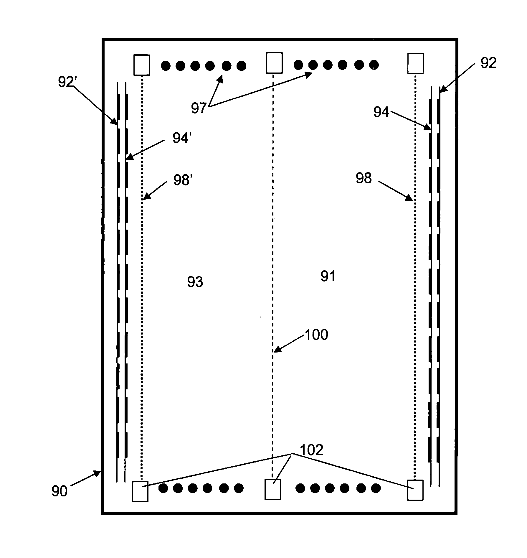
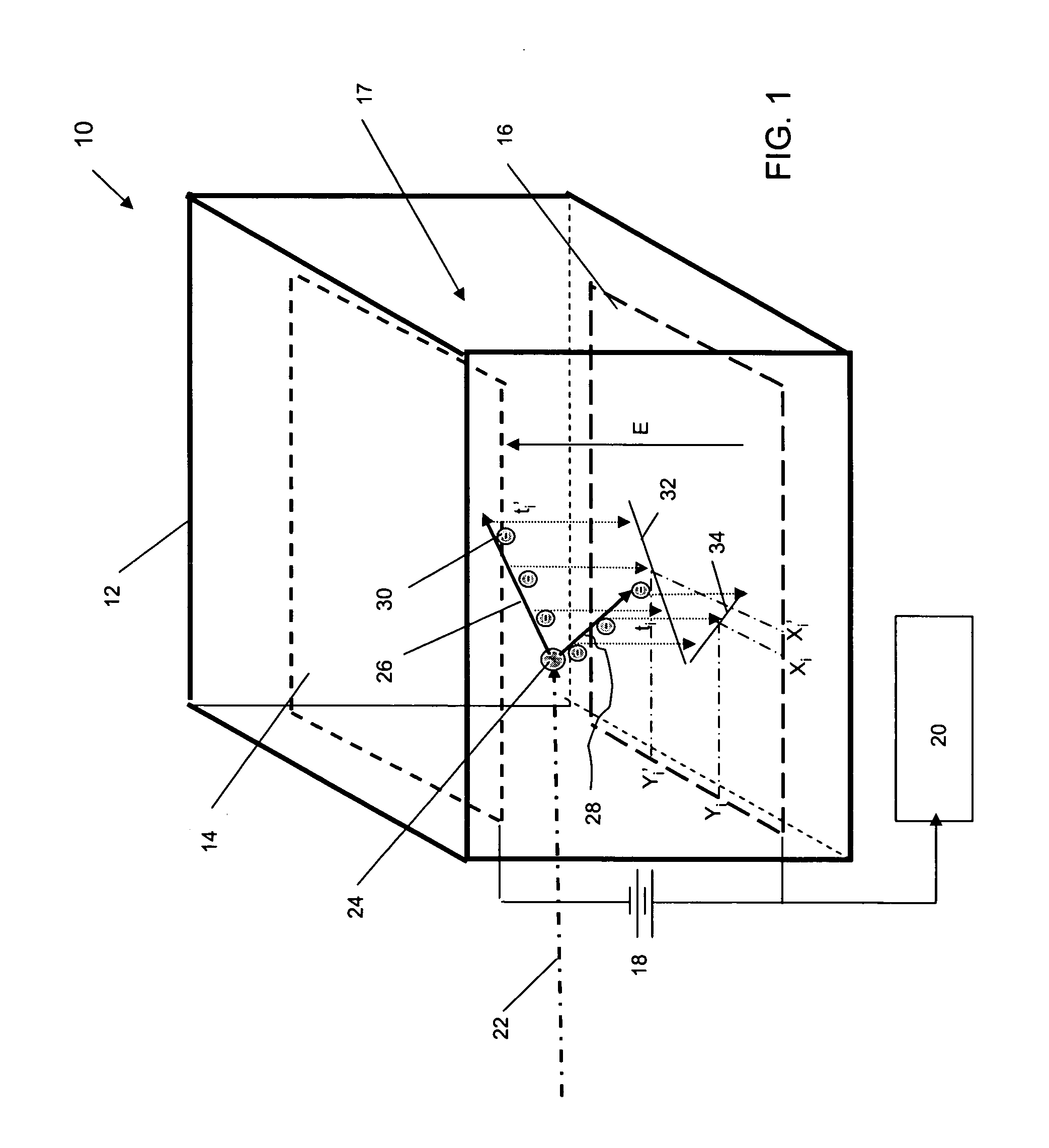
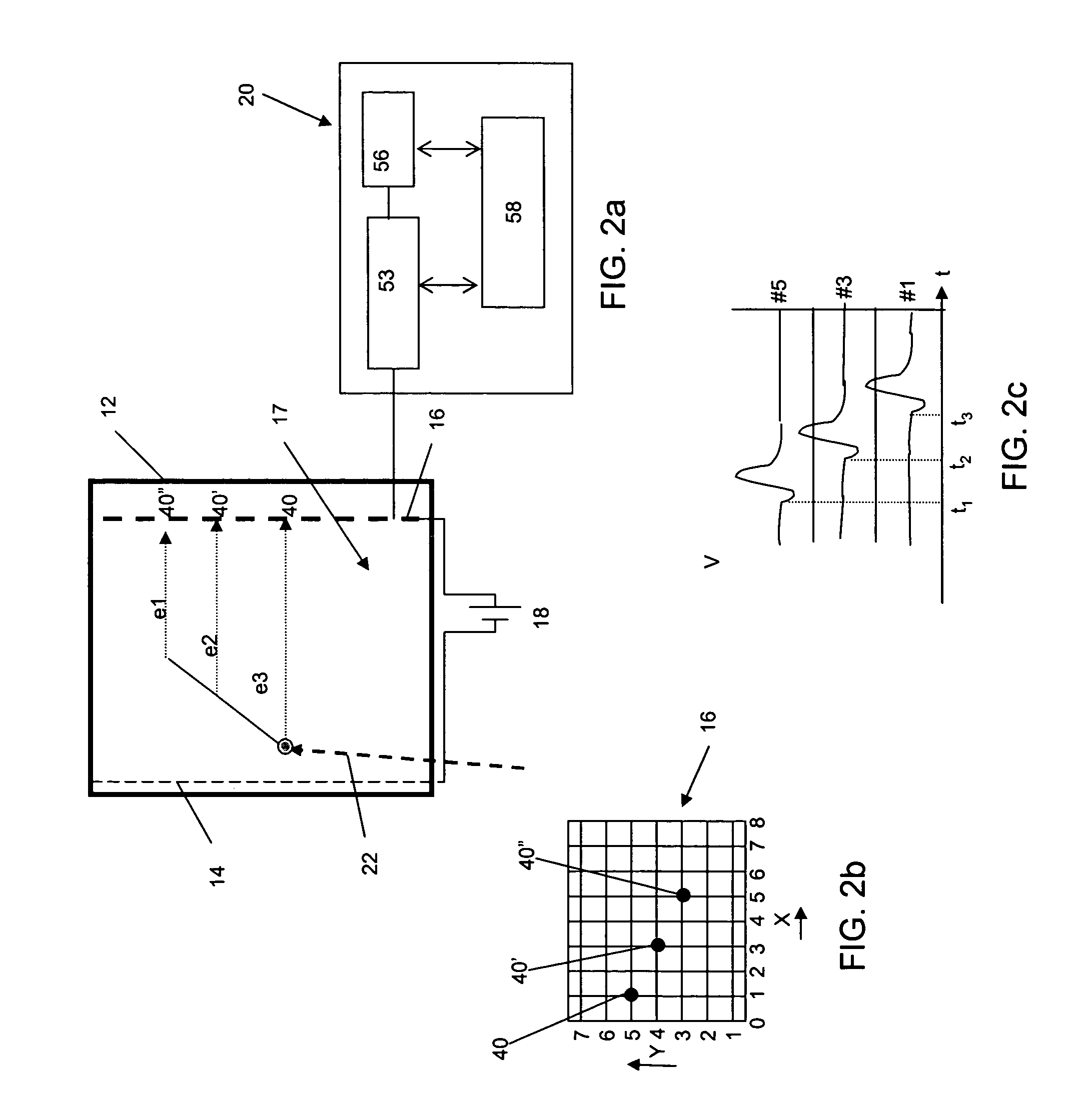
  • Neutron source detection camera
  • Neutron source detection camera
  • Neutron source detection camera

Examples


example

[0051] An incident neutron with 1 MeV kinetic energy (near peak of fission spectrum) is directed along the z (drift) axis. The chamber contains 10BF3 at 0.5 atmosphere. A collision of the neutron with 10BF3 produces (1) a Li track 7.58 mm long and generates approximately 71,600 primary ionizations, and (2) a 4He track 11.38 mm long containing approximately 79,400 primary ionizations. The range energy correlation is quite sufficient to identify which fragment is the He and which is the Li. If the 71,600 ion track were He rather than Li it would have to have a range of 10.2 mm, for example. The sum of the ionizations is divided by the well known “W” parameter (W=kinetic energy per ion pair) for BF3, minus the Q value of 2.79 MeV for the 10B reaction. This determines the neutron energy to an accuracy of about 4 per cent.

[0052] The kinematics of the reaction will result in the Li track being directed at approximately 38 degrees to the incident neutron direction, and the He track being ...


PUM


Abstract

A neutron imaging apparatus for obtaining an image of the general shape of a neutron emitting source and a bearing of the source relative to the apparatus, the apparatus comprising a chamber comprising a gas with a high probability of interacting with low energy neutrons, releasing collision products that maintain the neutron momentum, and generating ionization particles. The chamber comprises an electrode for providing an electronic signal indicative of the impact location of ionization particles on the electrode and a field to drift the ionization particles to the electrode. A readout indicates the location and time of impact of each ionization particle on the electrode; a memory stores a plurality of the electronic signals; and a computer receives and analyzes the signals and impact times and indicates the location of the source of neutrons by using back projection algorithms to calculate three-dimensional vectors indicative of the neutron path directions.

Description

FIELD OF THE INVENTION [0001] This invention relates to a method and associated apparatus for remotely locating a radiation source emitting neutrons by identifying the presence and travel path of neutrons arriving at a detection point. BACKGROUND OF THE INVENTION [0002] Transmission x-ray imaging is widely used for the detection of prohibited items within air and sea cargo containers, vehicles and railcars. However, while x-rays are extremely useful in identifying certain hidden objects, they are not very useful in identifying a wide variety of other potentially extremely dangerous items such as drugs, explosives and special nuclear materials (SNM). [0003] Transmission x-ray images become even less practical to use in open environments such as warehouses or the hold of cargo ships, etc. Furthermore considering that a particular prohibited material may be in a magnetic steel container as are commonly used in the shipping industry, the use of alternative techniques involving electroma...

Claims


Application Information

Patent Timeline
IPC IPC(8): G01T3/08G01T1/29G01T3/00
CPCG01T3/00G01T1/2935
Inventor MARTOFF, CHARLES JEFFREY
Owner TEMPLE UNIVERSITY
Learn More