Insertion fluid inspection device

a fluid inspection and fluid technology, applied in the direction of instruments, optical elements, applications, etc., can solve the problems of inability to accurately observe industrial processes, inability to provide the sharp focus that shorter lens length systems can provide, etc., to achieve improved lighting conditions, overcome adverse thermal effects, and improve quality

Active Publication Date: 2006-01-26
J M CANTY
View PDF14 Cites 17 Cited by
  • Summary
  • Abstract
  • Description
  • Claims
  • Application Information

AI Technical Summary

Benefits of technology

[0007] An object of the present invention is to provide an inspection device for inspecting a fluid in a vessel, in which a camera is insertable into the interior of the vessel. A further or alternate object of the present invention is to provide a inspection device suitable for a short lens length camera to provide high quality images of a fluid in the vessel and of particles within the fluid. A further or alternate object of the present invention is to provide improved lighting conditions for inspecting a fluid in a vessel. Another further or alternate object of the present invention is to provide an inspection device capable of inspecting fluids in a vessel that may be otherwise difficult to observe due to conditions such as high temperature, high pressure, volatility, toxicity, corrosiveness, etc. Yet another further or alternate object of the present invention is to overcome adverse thermal effects on a camera inserted into the interior of a vessel. Still another further or alternate object of the present invention is to provide a fluid inspection system capable of inspecting fluid in a gap between a lens and a light guide so that illumination is provided from behind the fluid at one or more angles.

Problems solved by technology

Many industrial processes, such as various manufacturing and chemical processes take place within closed or partially closed containers or vessels, making accurate observation of those industrial processes more difficult.
This is especially true where removal of product for inspection is not possible or practical, or where removal of the product would lead to inaccurate results due to the loss of process conditions.
Longer lens lengths cannot provide the sharp focus that shorter lens length systems can provide, particularly when precise observations are desired, such as when observing tiny particles suspended in the fluid which require sharper images as those provided by short lens length cameras.

Method used


Image

  • Insertion fluid inspection device
  • Insertion fluid inspection device
  • Insertion fluid inspection device

Examples


Embodiment Construction

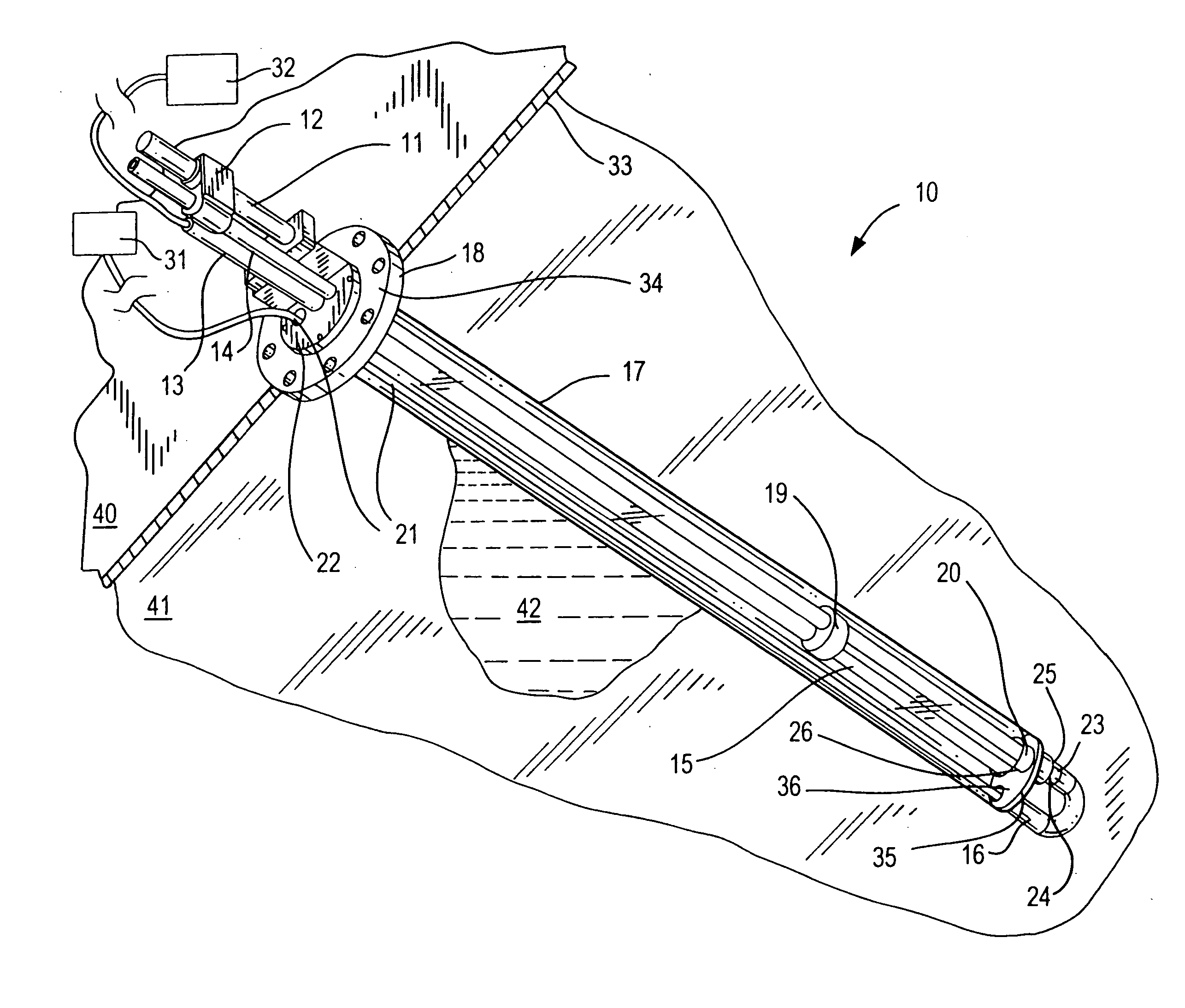
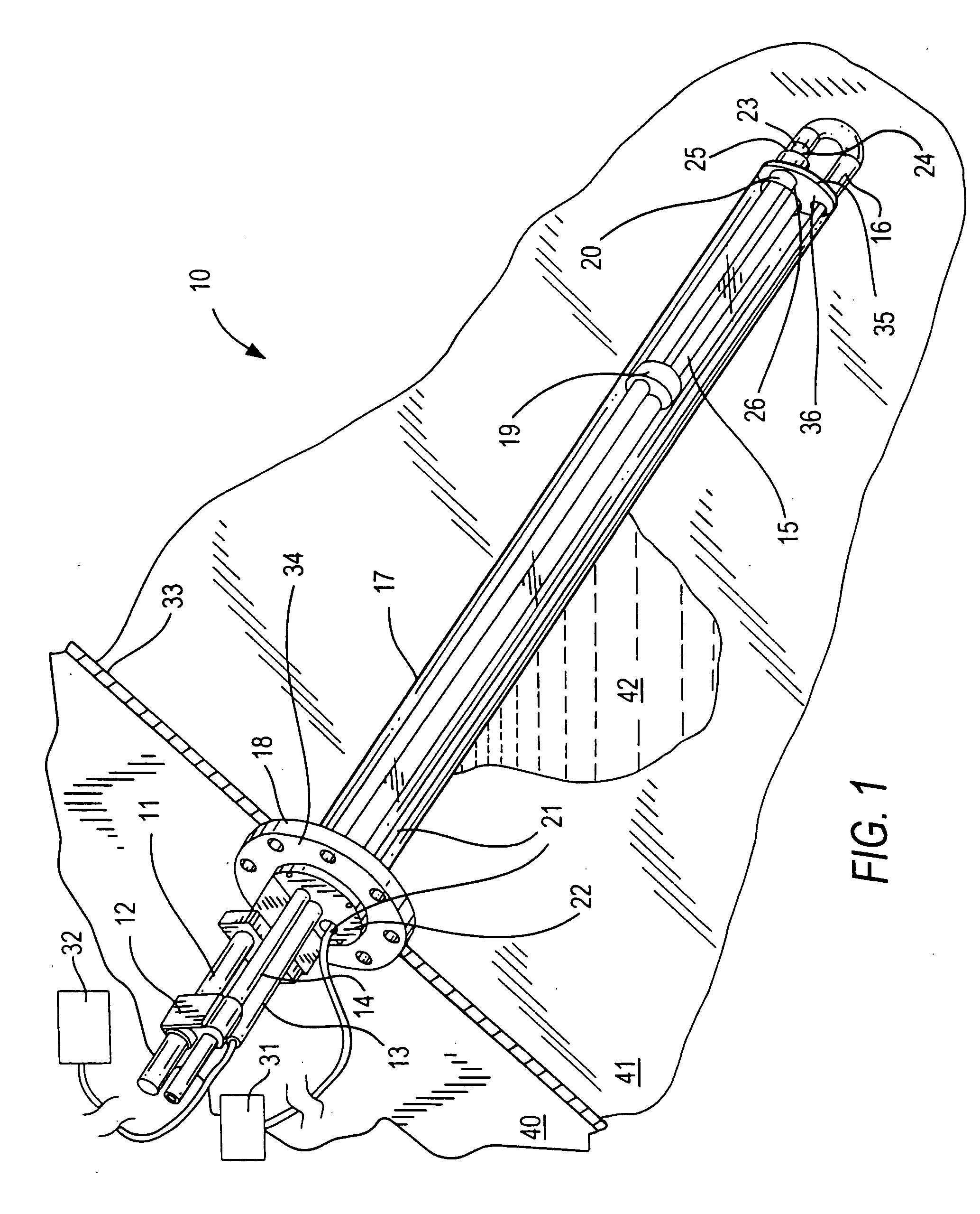
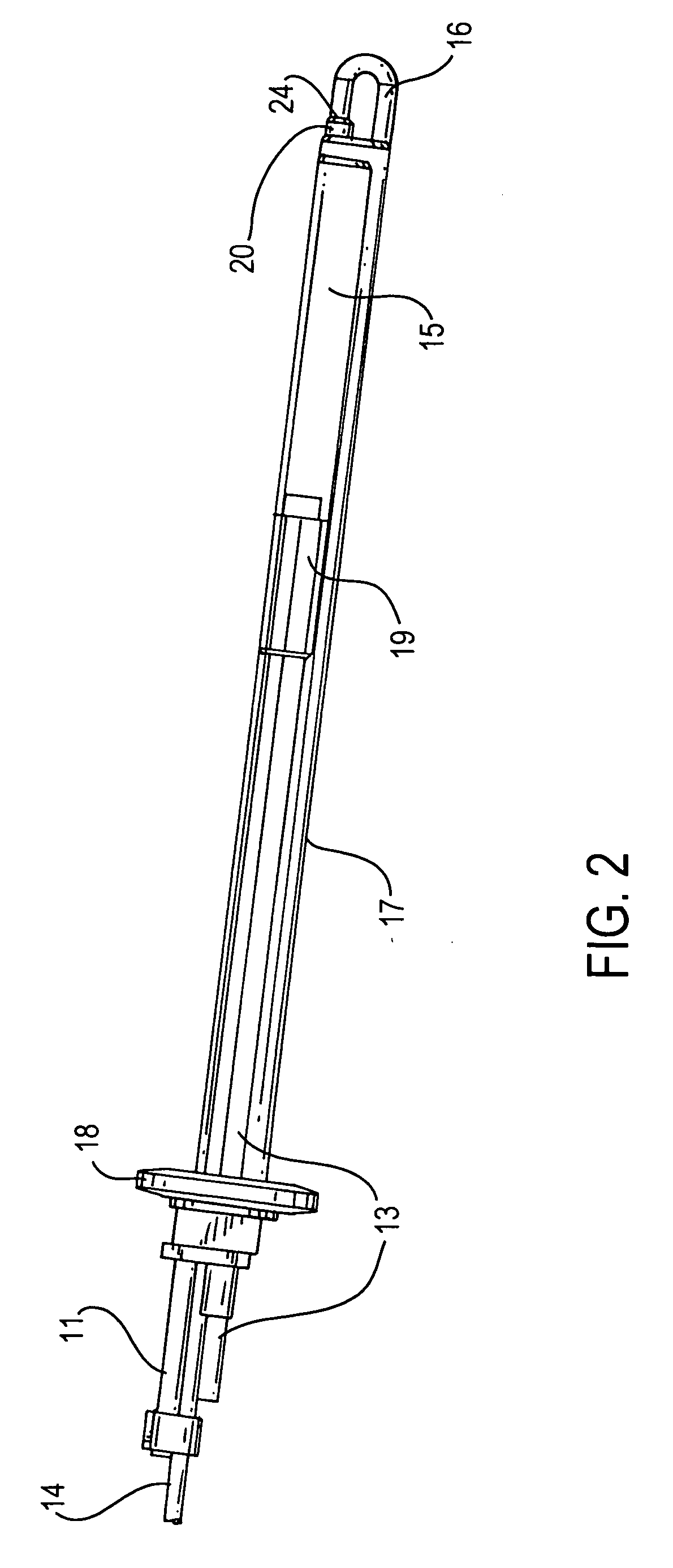
[0022] In FIG. 1, fluid inspection device 10 includes an elongated insertion well 17 that extends from rear end 34 at a wall 33 of the vessel, to front end 35 located within the vessel interior 41. The insertion well 17 is cylindrical in shape and is mounted at the rear end 34 to the vessel wall 33 in a sealing manner using, for example, flange mount 18, so that the inside of the insertion well is sealed off from fluid 42 and the outside of insertion well 17 is in contact with fluid 42. An instrument support bracket 22 is mounted to the flange mount 18 and can be used to support various external instruments of the inspection device 10.

[0023] A camera unit 15 is disposed inside of the insertion well 17 and is sealed off from the fluid 42. A lens 20 is disposed at front end 35 and extends through front end 35 so that a front end 25 of the lens 20 is in contact with the fluid 42 and a rear end of the lens 20 is inside of the insertion well 17 and in operative communication with the ca...


PUM

PropertyMeasurementUnit
angleaaaaaaaaaa
sizeaaaaaaaaaa
sizeaaaaaaaaaa

Abstract

A fluid inspection device for inspecting a fluid in a vessel includes an elongate insertion well having a rear end disposed at the wall of the vessel and a front end disposed in the interior of the vessel. An inside of the insertion well is sealed off from the fluid in the vessel and an outside of the insertion well is in contact with the fluid in the vessel. A camera unit is disposed in the inside of the insertion well, and a lens in operative communication with the camera unit is disposed at the front end of the insertion well so that a front end of the lens is in contact with the fluid and a rear end of the lens is inside the insertion well. In addition, a light guide having a light emitting end is configured to guide light from the inside of the insertion well to the light emitting end. The light emitting end is disposed forward of the front end of the lens and directs the light at an angle toward the front end of the lens, and a gap between the front end of the lens and the light emitting end is capable of receiving the fluid.

Description

[0001] The present invention relates to a fluid inspection device for inspecting a fluid in a vessel, and more particularly to a fluid inspection system having an insertion well extending into an interior of the vessel. The present invention also provides a method for inspecting a fluid in a vessel. BACKGROUND [0002] Many industrial processes, such as various manufacturing and chemical processes take place within closed or partially closed containers or vessels, making accurate observation of those industrial processes more difficult. Accurate observation of the processes within such vessels is desirable, for example, to enable improved control and / or industrial efficiency. This is especially true where removal of product for inspection is not possible or practical, or where removal of the product would lead to inaccurate results due to the loss of process conditions. [0003] It is known to use various devices for directly or remotely viewing the interior of a vessel, such as a press...

Claims


Application Information

Patent Timeline
Patent Type & Authority Applications(United States)
IPC IPC(8): G01N21/00A61B1/05G02B23/24
CPCG01N21/8507B01J2219/00268
Inventor CANTY, THOMAS M.O'BRIEN, PAUL J.
Owner J M CANTY
Why Eureka
Try Eureka