Three-dimensional surveying instrument and electronic storage medium

a three-dimensional and electronic storage medium technology, applied in the field of three-dimensional surveying instruments, can solve the problems of affecting the accuracy of the results, the size of the reference structure, and the difficulty of positioning the measurement of the position of the reference structure and the camera,

Inactive Publication Date: 2006-01-26
KK TOPCON
View PDF3 Cites 53 Cited by
  • Summary
  • Abstract
  • Description
  • Claims
  • Application Information

AI Technical Summary

Problems solved by technology

Placing the reference structure and the camera, and measuring positions thereof, are very troublesome.
In the case of a building, or the like, its dimensions are gigantic, which is accompanied by great difficulty.
Moreover, an imaging posture cannot be measured without providing the camera with the inclinometer for detecting a tilt.
Such a special camera, therefore, becomes extremely expensive.

Method used


Image

  • Three-dimensional surveying instrument and electronic storage medium
  • Three-dimensional surveying instrument and electronic storage medium
  • Three-dimensional surveying instrument and electronic storage medium

Examples


first embodiment

[0022] The first embodiment will be described with reference to FIGS. 1 through 4.

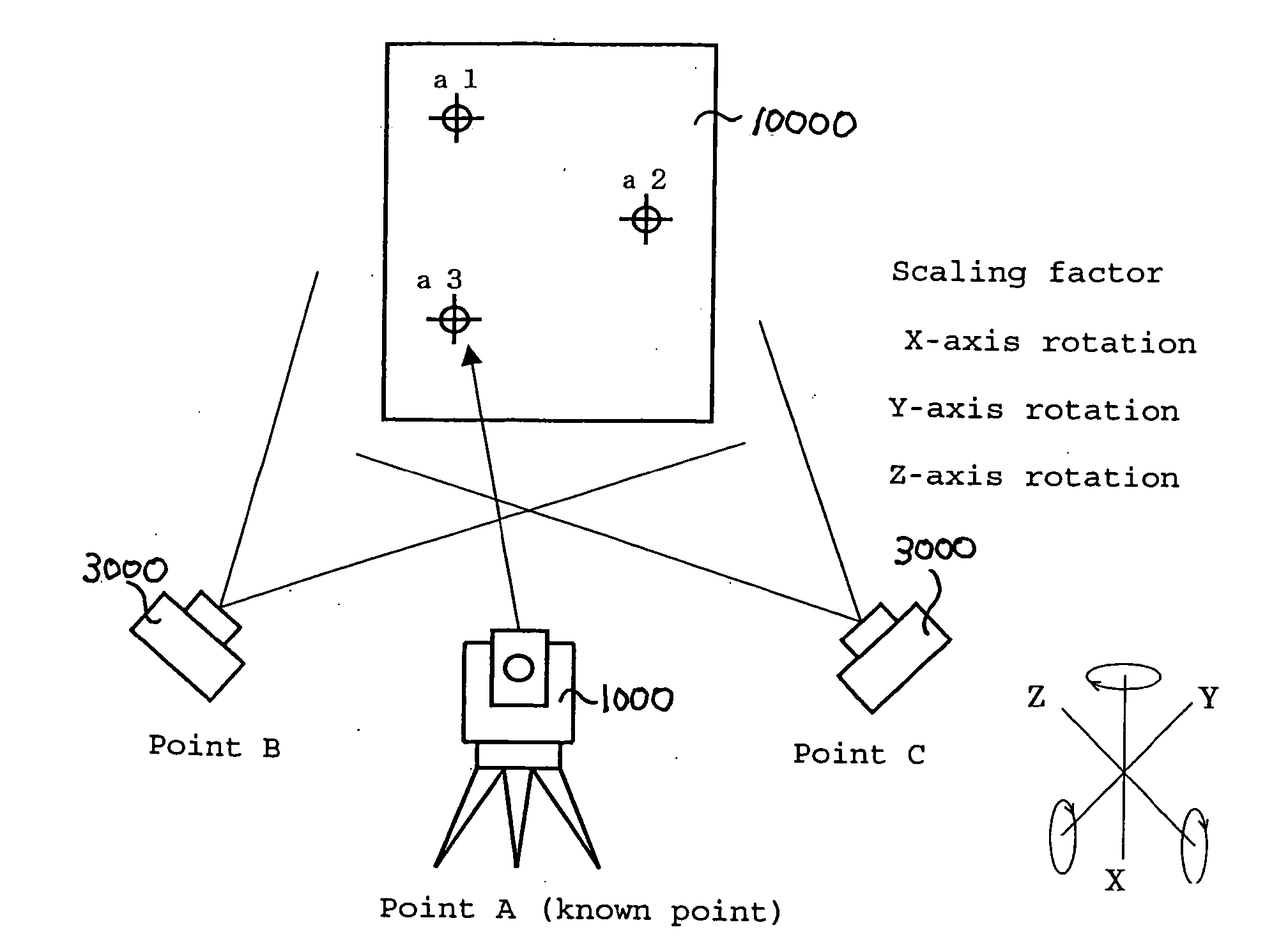
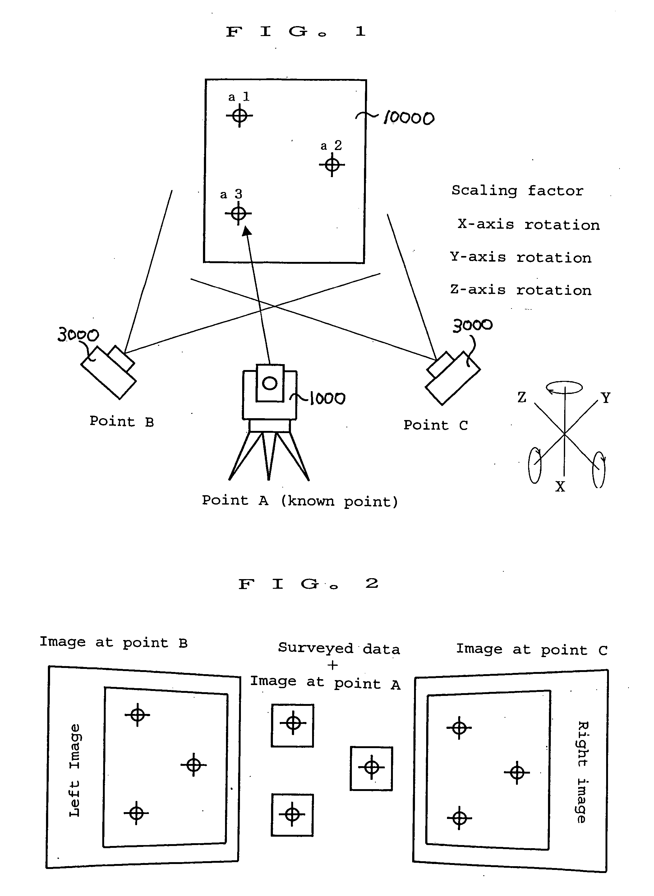
[0023] The first embodiment in which a target mark is not used as a path point will be described with reference to FIGS. 1 and 2. In this first embodiment, the surveying instrument 1000 is equipped with the imaging unit 100.

[0024] The surveying instrument 1000 comprises the imaging unit 100 capable of inputting an image in a collimation direction. As a distance measuring function, the surveying instrument 1000 has a non-prism function that catches a direct reflection from a natural object, and that does not require a reflecting prism.

[0025] The surveying instrument 1000 collimates an arbitrary part of a target to be measured so that the distance is measured. In addition, the surveying instrument 1000 also measures a horizontal angle and an angular height in like manner. Then, the imaging unit 100 acquires an image at a surveying point. Because a collimation point is the center of an optical axis, th...

second embodiment

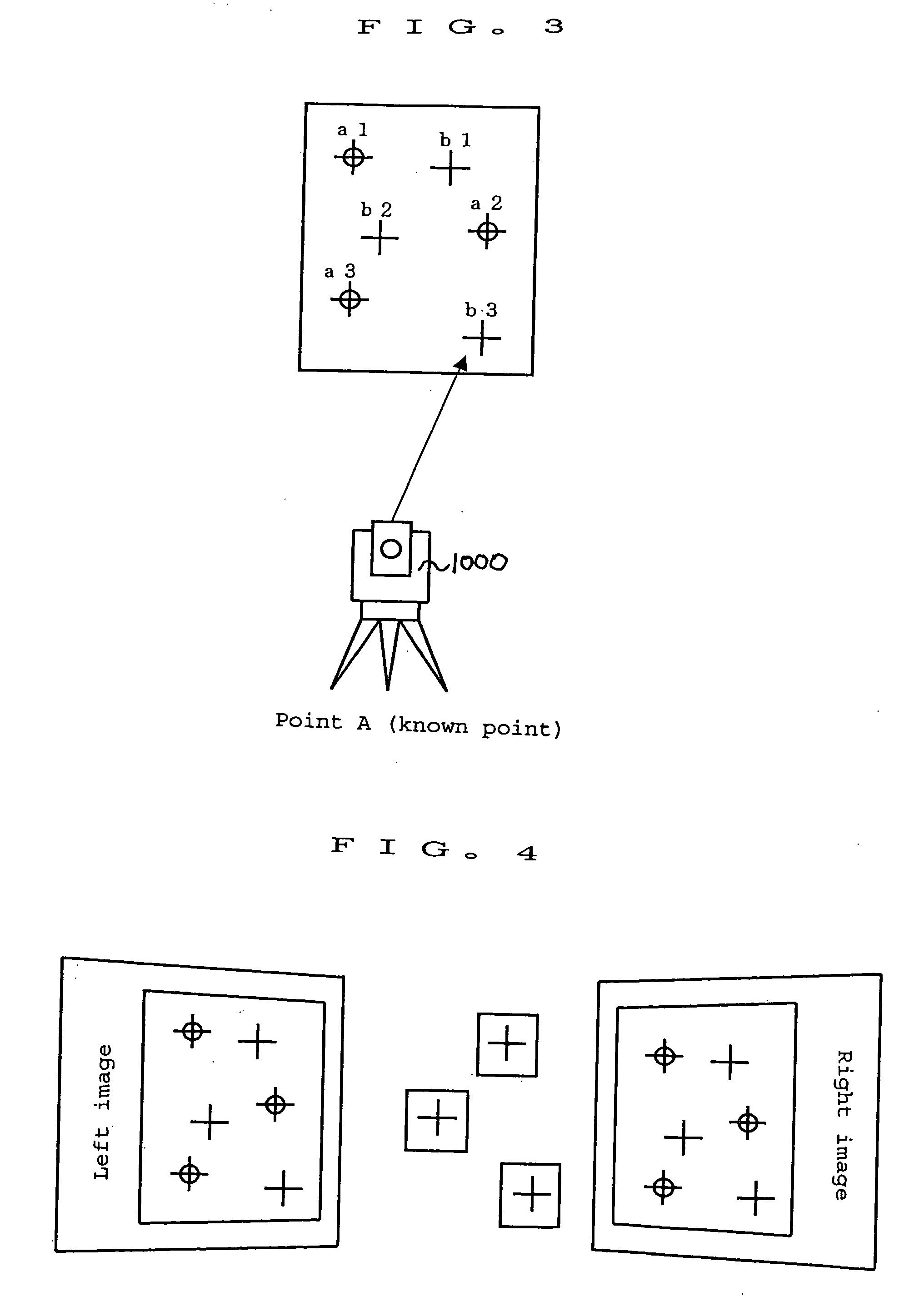
[0064] A second embodiment relates to a three-dimensional surveying instrument that uses target marks for three reference points that become path points.

[0065] A total station capable of measuring the distance to a reflecting prism which is placed at the reference points is used as the surveying instrument 1000. In addition, instead of the reflecting prism, it is also possible to use such a target mark that a mark is drawn on a reflection sheet.

[0066] Incidentally, an example of the relationship between data measured by the surveying instrument 1000 and an image acquired by the digital camera 3000 will be described as below. x=-f⁢ ⁢a11⁢(X-Xc)+a12⁡(Y-Yc)+a13⁡(Z-Zc)a31⁡(X-Xc)+a32⁡(Y-Yc)+a33⁡(Z-Zc)⁢⁢y=-f⁢ ⁢a21⁢(X-Xc)+a22⁡(Y-Yc)+a23⁡(Z-Zc)a31⁡(X-Xc)+a32⁡(Y-Yc)+a33⁡(Z-Zc)Equation⁢ ⁢1[0067] where: f is the focal length of the digital camera 3000; a is (ω, φ, K—roll, pitch, angle of yaw), which is a tilt (rotation angles of three axes) of the digital camera 3000; (X, Y, Z) is three-dime...


PUM


Abstract

The present invention relates to a three-dimensional surveying instrument used to calculate three-dimensional coordinate data by use of a surveying instrument and an imaging unit. An object of the present invention is in particular to provide a three-dimensional surveying instrument that determines positions of corresponding points by use of a surveying instrument, and that is capable of stereo displaying. The three-dimensional surveying instrument according to the present invention is capable of: from positions of at least three reference points, which are measured by the surveying instrument, and from an image acquired by the imaging unit, calculating a tilt of the imaging unit, and the like; from a position of a collimation point measured by the surveying instrument, calculating a tilt of the imaging unit, and the like; with the collimation point being used as a corresponding point, performing matching of the image acquired by the imaging unit; associating the position of the collimation point measured by the surveying instrument with a collimation point on the image, the matching of which has been performed; and calculating three-dimensional coordinate data of the target to be measured on the basis of the association.

Description

BACKGROUND OF THE INVENTION [0001] The present invention relates to a three-dimensional surveying instrument used to calculate three-dimensional coordinate data by use of a surveying instrument and an imaging unit, and more particularly to a three-dimensional surveying instrument that is capable of determining positions of corresponding points by use of a surveying instrument at a surveying site so as to generate data, stereo displaying of which can be performed. [0002] Heretofore, when three-dimensional coordinates are acquired from image data, it is necessary to use, for example, imaging means such as a digital camera, and a reference structure, the dimensions of which are known. The reference structure is placed in proximity to an object that is a target to be measured. Then, this reference structure is imaged by a camera from two directions or from a plurality of directions. This camera is equipped with an inclinometer used to measure a tilt of an image in the front and back, an...

Claims


Application Information

Patent Timeline
Patent Type & Authority Applications(United States)
IPC IPC(8): G01B11/24G01C11/06G01C15/00
CPCG01C1/04G01C15/00G01C11/06
Inventor OHTOMO, FUMIOOHTANI, HITOSHI
Owner KK TOPCON
Why Eureka
Try Eureka