
Pipe pulling device

a technology of pipe pulling and pipe laying, which is applied in the directions of pipe laying and repair, mechanical equipment, transportation and packaging, etc., to achieve the effect of facilitating assembly and minimizing cos

Inactive Publication Date: 2006-01-26
HUNCOVSKY JEFFERY W
View PDF15 Cites 8 Cited by
  • Summary
  • Abstract
  • Description
  • Claims
  • Application Information

AI Technical Summary

Benefits of technology

[0017] Another object is to provide such a device that is easy to assemble.

Problems solved by technology

While the above-described devices fulfill their respective, particular objectives and requirements, the aforementioned patents do not describe a pipe pulling device that grasps a pipe without a hammer strike.

Method used


Image

  • Pipe pulling device
  • Pipe pulling device
  • Pipe pulling device

Examples


Embodiment Construction

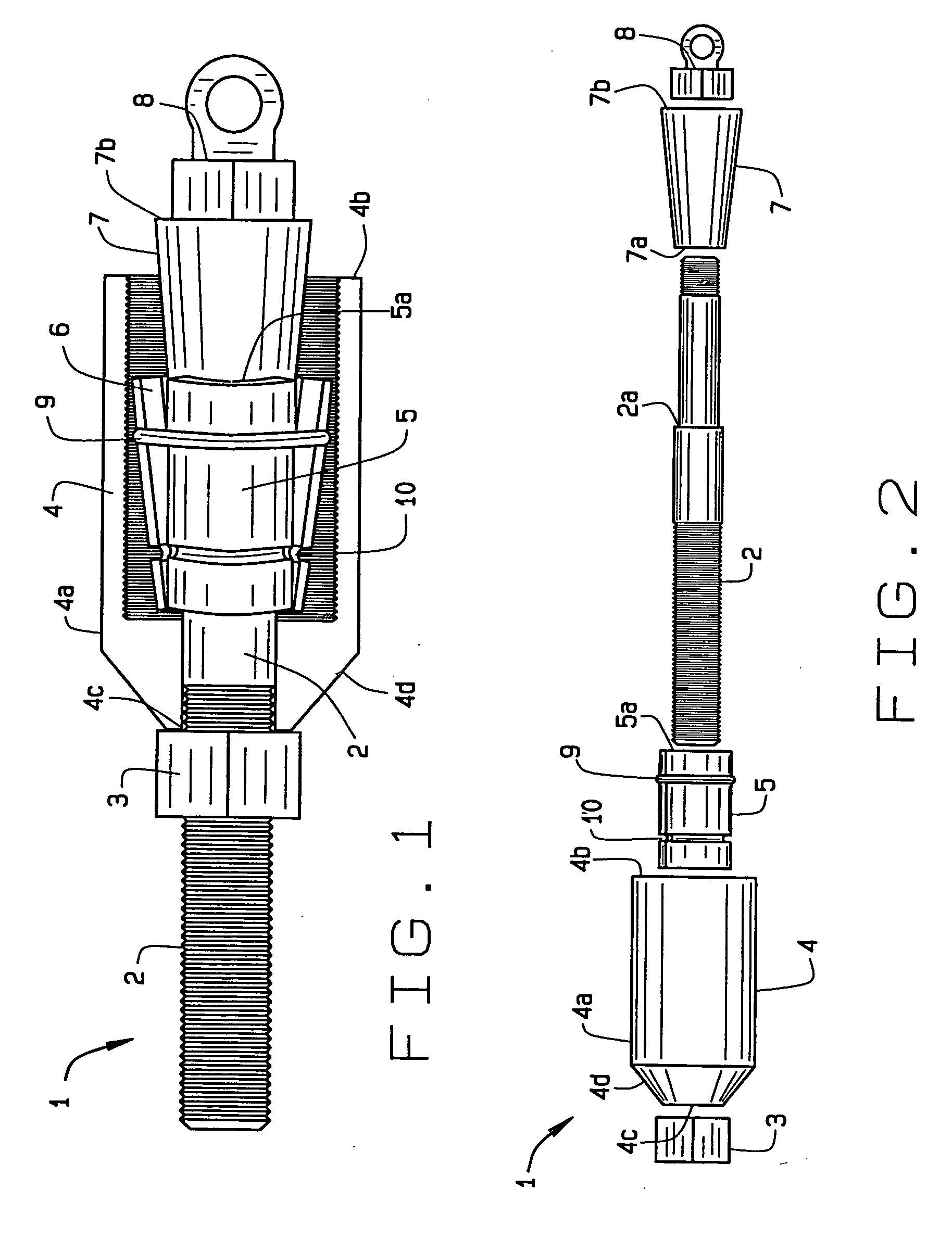
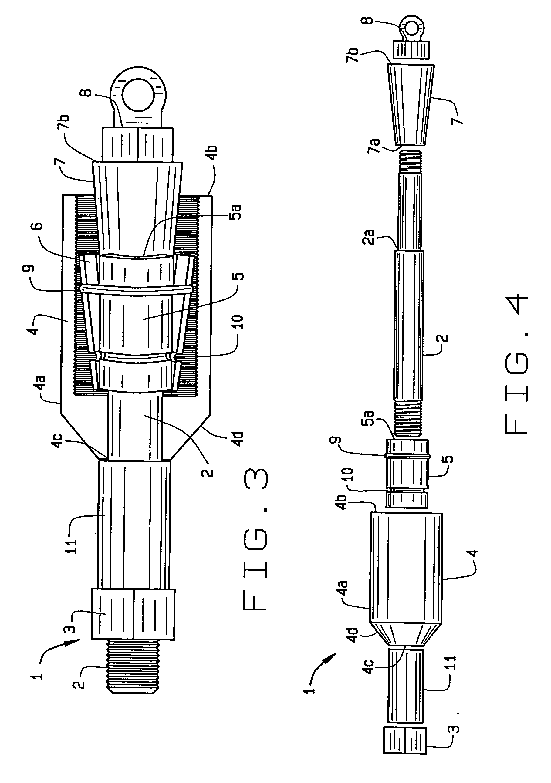
[0029] The present art overcomes the prior art limitations by providing wedge vanes that expand under mechanical action to grasp a pipe within a housing. A contractor pulls the present invention through the soil, pulling pipe behind it. The direction of pull is denoted forward in references to the present invention, generally opposite the pipe. Beginning on FIG. 1, the preferred embodiment of the pipe pulling device 1 has a shaft 2, a nut 3 upon the shaft 2, an housing 4 upon the shaft 2 and rearward of the nut 3, a wedge 5 upon the shaft 2 and within the housing 4, a cone 7 upon the shaft 2 and advancing into the wedge 5, and an eye nut 8 upon the shaft 2 and behind the cone 7. The shaft 2, generally cylindrical steel, has threading for the nut 3 at the front and the eye nut 8 at the rear. The shaft 2 generally exceeds the housing 4 in length with at least two nut 3 diameter's length of threading on the front for connecting with pulling equipment such as a plow, tractor, or bulldoz...


PUM


Abstract

A pipe pulling device secures to the end of a pipe, with wedge action, for pulling by equipment. The device has a shaft, a housing upon the shaft, one or more wedges, a cone, nuts, eye nuts, O rings, and a sleeve, all arranged coaxially. First the nut is placed upon the shaft, then the housing is oriented forward. The forward end of the housing has a beveled edge to assist in passage through soil. The contractor then places a wedge of three vanes upon the shaft within the housing. A hollow cone upon the shaft contacts the wedge. An eye nut then secures the assembled parts upon the shaft. In use, a contractor tightens the nut rearward thus pulling the cone forward and expanding the wedge. The Is wedge expands to grasp the pipe between the housing and the wedge. The contractor can then pull the pipe through soil.

Description

CROSS REFERENCE TO RELATED APPLICATION [0001] This nonprovisional patent application claims priority to the provisional patent application having Ser. No. 60 / 589,745, which was filed on Jul. 20, 2004.BACKGROUND OF THE INVENTION [0002] The pipe pulling device relates to entrenching equipment in general and more specifically to connecting plastic pipe to a pulling machine. Plastic pipe fits within a housing and one or more wedges fit within the plastic pipe. Advancing a shaft within the pipe and through the wedges compresses the pipe between the wedges and the housing. Pulling on the shaft then pulls the pipe through the soil for entrenching. [0003] Contractors, utilities, and earthmovers have entrenched pipe, cable, and lines across the land. Buried lines leave a clean landscape and have less disruption to the utilities located within the buried line and on easements. Buried lines suffer less from vandals and the elements. Contractors have dug trenches and then buried lines within th...

Claims


Application Information

Patent Timeline
IPC IPC(8): F16L1/12E02D5/10
CPCF16L1/06F16L1/028
Inventor HUNCOVSKY, JEFFERY W.
Owner HUNCOVSKY JEFFERY W
Learn More