
Radio communication device and associated coupling structure comprising at least one conductor board and at least one flat antenna coupled thereto

Inactive Publication Date: 2006-01-26
SIEMENS AG
View PDF0 Cites 60 Cited by
  • Summary
  • Abstract
  • Description
  • Claims
  • Application Information

AI Technical Summary

Benefits of technology

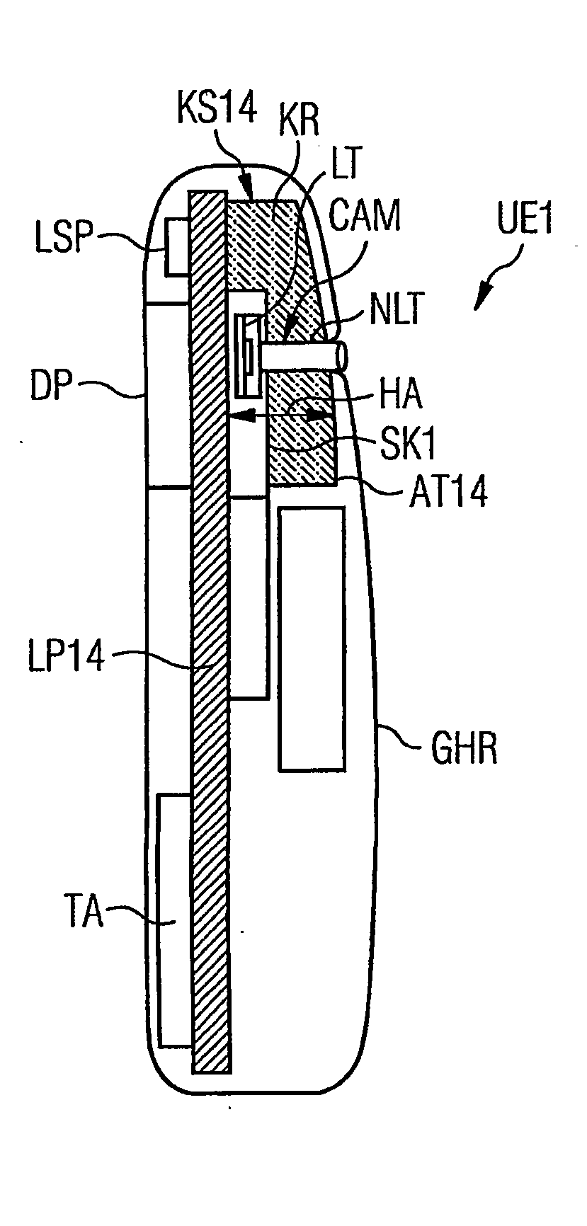
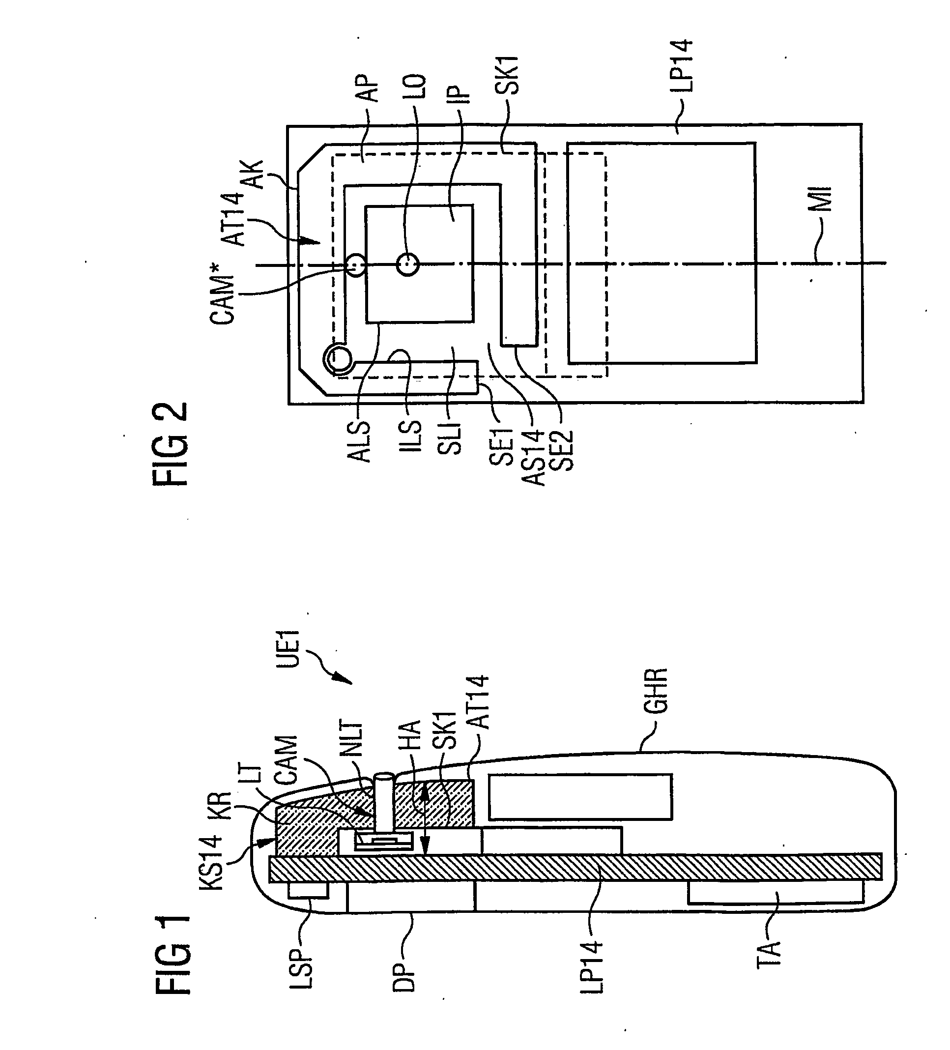
[0004] The coupling area which is available and required in any event between the circuit board and the flat antenna coupled to it transmitting and / or receiving the radio fields thus will be utilized partly or completely by the camera so that, overall, an largely densely packed or compact, space-saving coupling unit consisting of a circuit board, a flat antenna and a camera is produced. Since the camera is partly or completely a component of the existing antenna volume of the coupling structure, the original housing dimensions of the radio communication device without the camera can be retained even after the additional camera has been installed or even can be reduced. The additional installation of the camera in or on the coupling area of the coupling structure causes hardly any or no antenna volume of the coupling structure to be lost so that radio fields can be sent and / or received without any problem. This dual utilization of the coupling area, in particular, allows shorter designs of the housing to be used for the radio communication device.

Problems solved by technology

If there is also a requirement for fitting a camera into such a communication device, further space would be required within its housing which would not be available there as a result of the high packing densities of functional components.
The only possible way of accommodating the camera would be by increasing the dimensions of the housing, which would make the device unattractive.

Method used


Image

  • Radio communication device and associated coupling structure comprising at least one conductor board and at least one flat antenna coupled thereto
  • Radio communication device and associated coupling structure comprising at least one conductor board and at least one flat antenna coupled thereto
  • Radio communication device and associated coupling structure comprising at least one conductor board and at least one flat antenna coupled thereto

Examples


Embodiment Construction

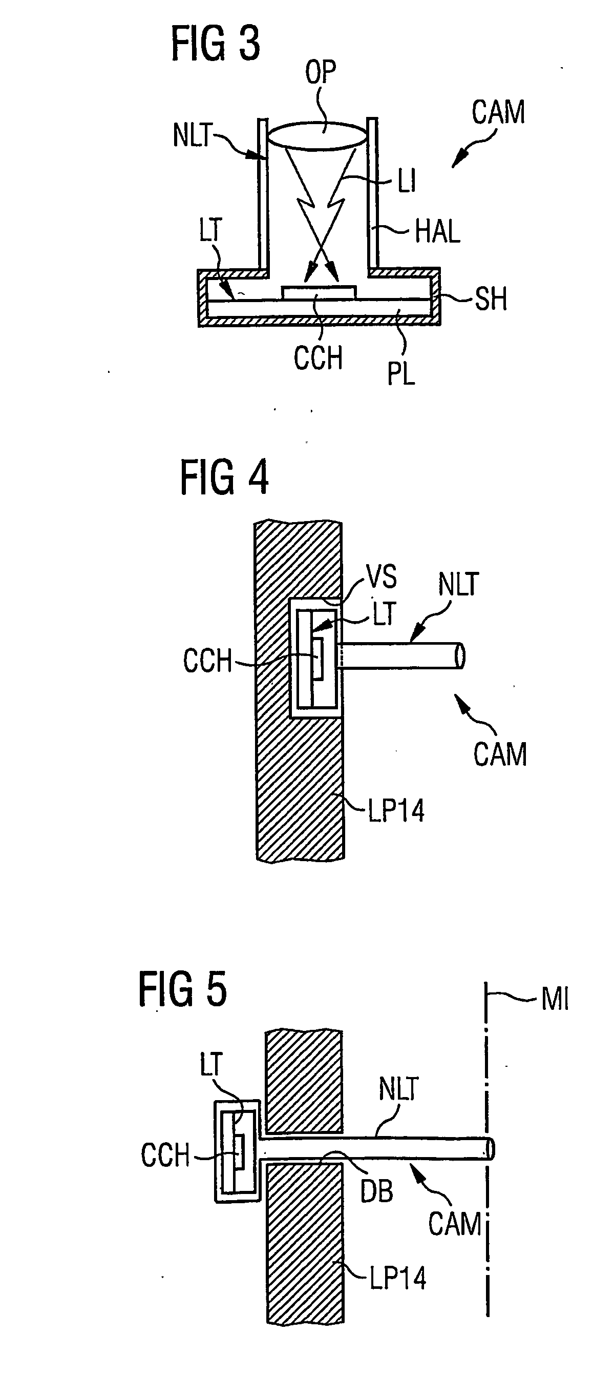
[0014]FIG. 1 shows a schematic diagram of a lengthwise section seen from one side of a first radio communication device UE1. This radio communication device UE1 features in its housing GHR a circuit board LP14 to which a flat antenna RT14 is coupled, forming a coupling structure KS14. This flat antenna AT14 integrated into the housing GHR is arranged at a distance EA to the component mounting surface of the circuit board LP14. It is assigned here to the back of the circuit board LP14; i.e., which is the bits of the circuit board which are opposite the operation components such as the loudspeaker / microphone unit LSP, display or screen device DP, or keyboard. In this way, the flat antenna AT14 is held away from the user's head if the radio communication device UE1 is used in accordance with specifications and emits its radio waves largely freely in the space and receives radio fields largely freely as well. The flat antenna AT14 is positioned in the upper half of the circuit board LP1...


PUM


Abstract

A radio communication device is provided which includes a conductor board and a flat antenna disposed in the housing thereof and arranged at a distance from each other, thereby forming a coupling structure. A coupling area with a predetermined antenna volume is contained in the coupling structure between the antenna and the conductor board. At least one camera is arranged in, or adjacent to, the coupling area of the coupling structure such that they simultaneously form a component of the antenna volume of the coupling structure.

Description

BACKGROUND OF THE INVENTION [0001] The present invention relates to a radio communication device and associated coupling structure having at least one circuit board and at least one flat antenna in its housing which are arranged at a distance from each other, thereby forming a coupling structure, with a coupling area having a specifiable antenna volume being enclosed between the flat antenna and the circuit board. [0002] The trend with radio communication devices, especially mobile communication devices, is towards ever smaller models boasting ever more components and service features. Thus, in addition to the functional components such as display, keyboard, high-frequency module, baseband unit, etc., there also may be a flat antenna integrated into the housing of a radio communication device to mechanically protect the antenna. In this case, a specific volume of space is occupied which is also necessary between the flat antenna and the circuit board to enable a radio field to be tr...

Claims


Application Information

Patent Timeline
IPC IPC(8): H04Q7/20H01Q1/24H01Q1/38H01Q1/44H04B1/38H04M1/02H04N7/14
CPCH01Q1/243H01Q1/38H01Q1/44H04N2007/145H04M1/0264H04M2250/20H04N7/142H04B1/3833
Inventor BRUNEL, ROMANFRIEDERICH, ALEXANDERHUBER, STEFANKOWALSKI, THORSTENOELSCHLAGER, MARTINPINTO, ALEXANDRESCHREIBER, MICHAELSIEBINGER, STEFAN
Owner SIEMENS AG
Learn More