Expandable framework with overlapping connectors

Inactive Publication Date: 2006-01-26
BOSTON SCI SCIMED INC
View PDF19 Cites 77 Cited by
  • Summary
  • Abstract
  • Description
  • Claims
  • Application Information

AI Technical Summary

Benefits of technology

[0021] In some embodiments, when curvature is applied to the stent along its length, the second connector and the third connector may move away from one another, and the first connector and the second connector may move toward one another. Each c

Problems solved by technology

If the amount of curvature is further in

Method used


Image

  • Expandable framework with overlapping connectors
  • Expandable framework with overlapping connectors
  • Expandable framework with overlapping connectors

Examples


Embodiment Construction

[0033] While this invention may be embodied in many different forms, there are described in detail herein specific embodiments of the invention. This description is an exemplification of the principles of the invention and is not intended to limit the invention to the particular embodiments illustrated.

[0034] For the purposes of this disclosure, like reference numerals in the figures shall refer to like features unless otherwise indicated.

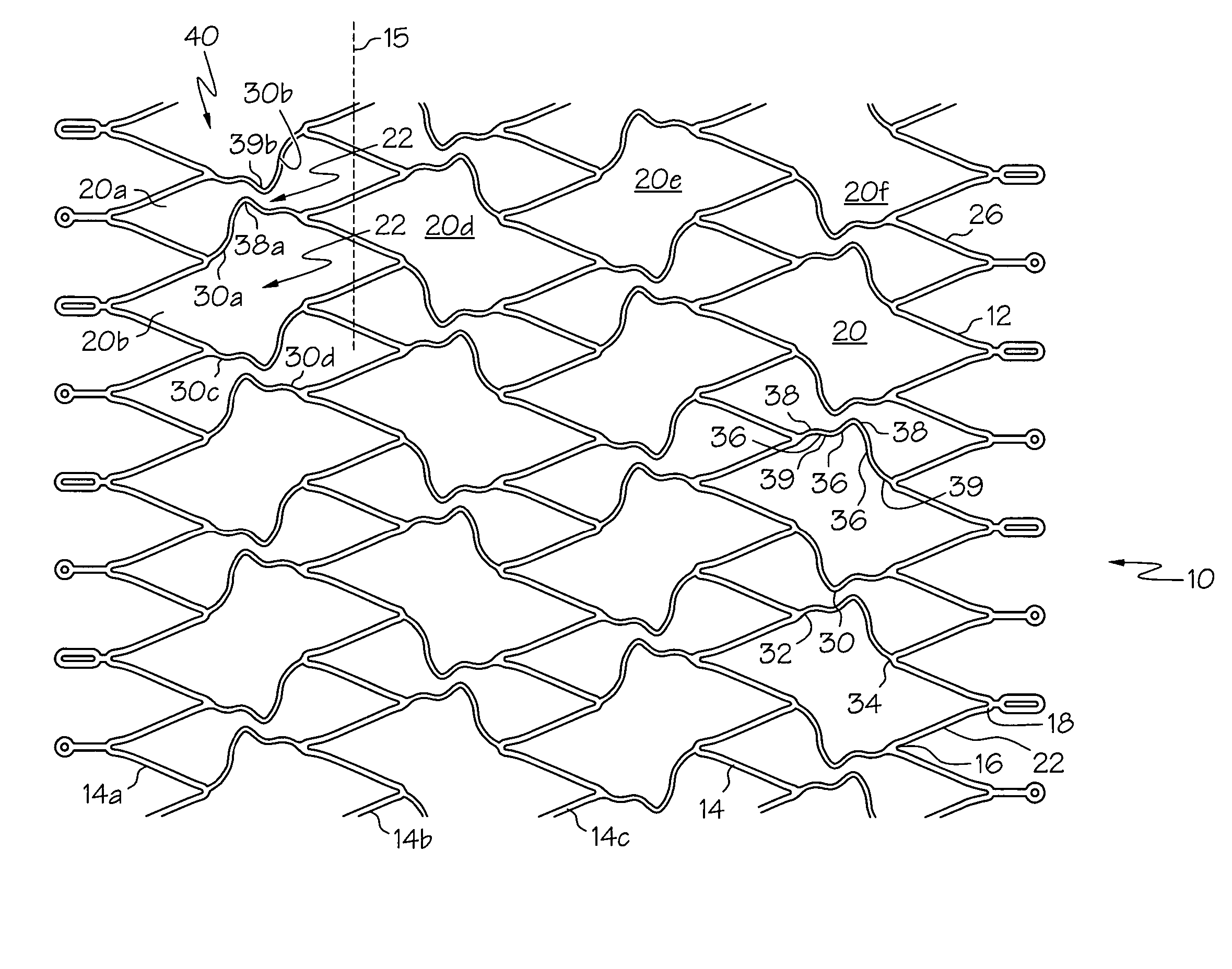
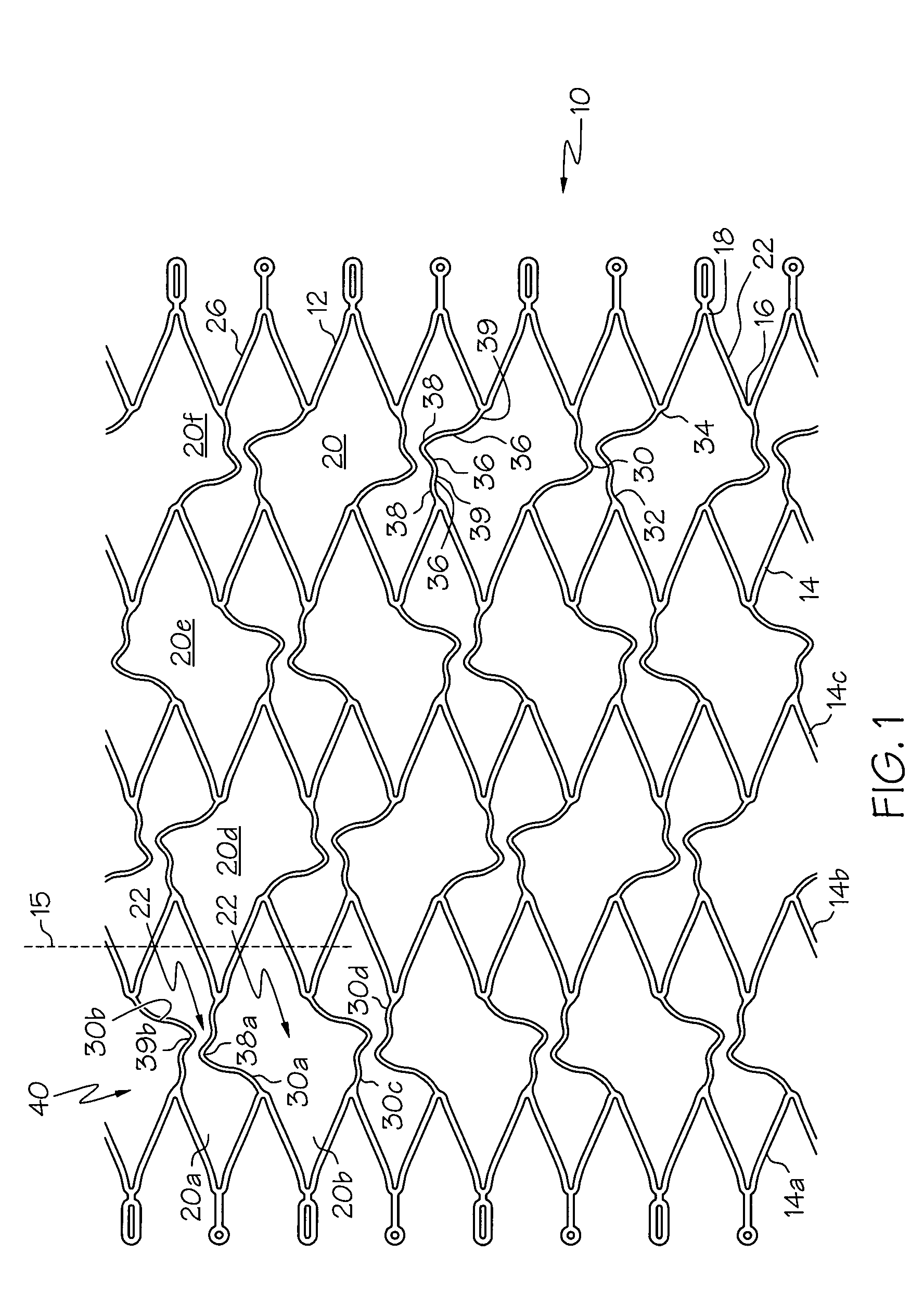
[0035] The term “stent” as used herein is intended to encompass traditional stents suitable for supporting a vessel wall and other expandable framework or expanded devices for use within a bodily lumen. For example, an expandable framework according to the invention may be used to position and hold Guglielmi detachable coils. In some embodiments, an expandable framework for use with Guglielmi detachable coils may not be intended for supporting a vessel wall. Any shape configuration described herein may be used in some embodiments to form a stent ...


PUM


Abstract

A stent may comprise a plurality of serpentine bands and connectors. A first connector may overlap a second connector when the stent is unexpanded. The first connector may also overlap the second connector in an unexpanded state when the stent is subject to compressive forces in the local area of the connectors, such as when the connectors are located on the inside of a curve. The second connector may be shaped according to a rotation of the first connector about the centroid of the cell between the first connector and the second connector.

Description

BACKGROUND OF THE INVENTION [0001] The use of stents in bodily lumen is well known. A stent is typically delivered in an unexpanded state to a desired location in a bodily lumen via a stent delivery device such as a catheter. Once the stent is at the desired bodily location, it is either expanded with a balloon or other suitable device or allowed to expand by, for example, withdrawing a restraining sheath. [0002] Some stents may be used to place Guglielmi electrolytically detachable coils, for example as described in U.S. Pat. No. 5,947,962, incorporated herein by reference. [0003] Stents are desirably flexible in order to be delivered through a tortuous anatomy. As the amount of curvature along the length of a stent is increased, some stents may reach a point where adjacent struts contact one another. If the amount of curvature is further increased, the stent may undesirably kink. [0004] There remains a need for a stent that may be maneuvered through areas of high curvature. There ...

Claims


Application Information

Patent Timeline
IPC IPC(8): A61F2/06A61F2/82
CPCA61F2/91A61F2/915A61F2230/0054A61F2002/91533A61F2002/91558A61F2002/828
Inventor LEYNOV, ALEXANDERHUI, DELILAH YINBARRY, DAVID
Owner BOSTON SCI SCIMED INC
Why Eureka
Try Eureka