
Electric puffs

a technology of electric puffs and puffs, applied in the field of electric puffs, can solve the problems of not keeping a user's, cosmetics may not be evenly applied to the desired body part, and it is difficult for users to do user's makeup

Inactive Publication Date: 2006-02-02
CHOO YOON JEONG
View PDF3 Cites 6 Cited by
  • Summary
  • Abstract
  • Description
  • Claims
  • Application Information

AI Technical Summary

Benefits of technology

[0008] Accordingly, the present invention has been made keeping in mind the above problems occurring in the prior art, and an object of the present invention is to provide an electric puff, intended to evenly and rapidly apply a cosmetic to a desired body part with a constant force, although a user does not reciprocate the puff by hand.

Problems solved by technology

The conventional puff is problematic in that a user must dab a surface covered with a cosmetic on a desired body part by hand, so that it is very complicated to do a user's makeup.
Further, since it is difficult to keep a user's force constant, the cosmetic may not be evenly applied to the desired body part.

Method used


Image

  • Electric puffs
  • Electric puffs
  • Electric puffs

Examples


first embodiment

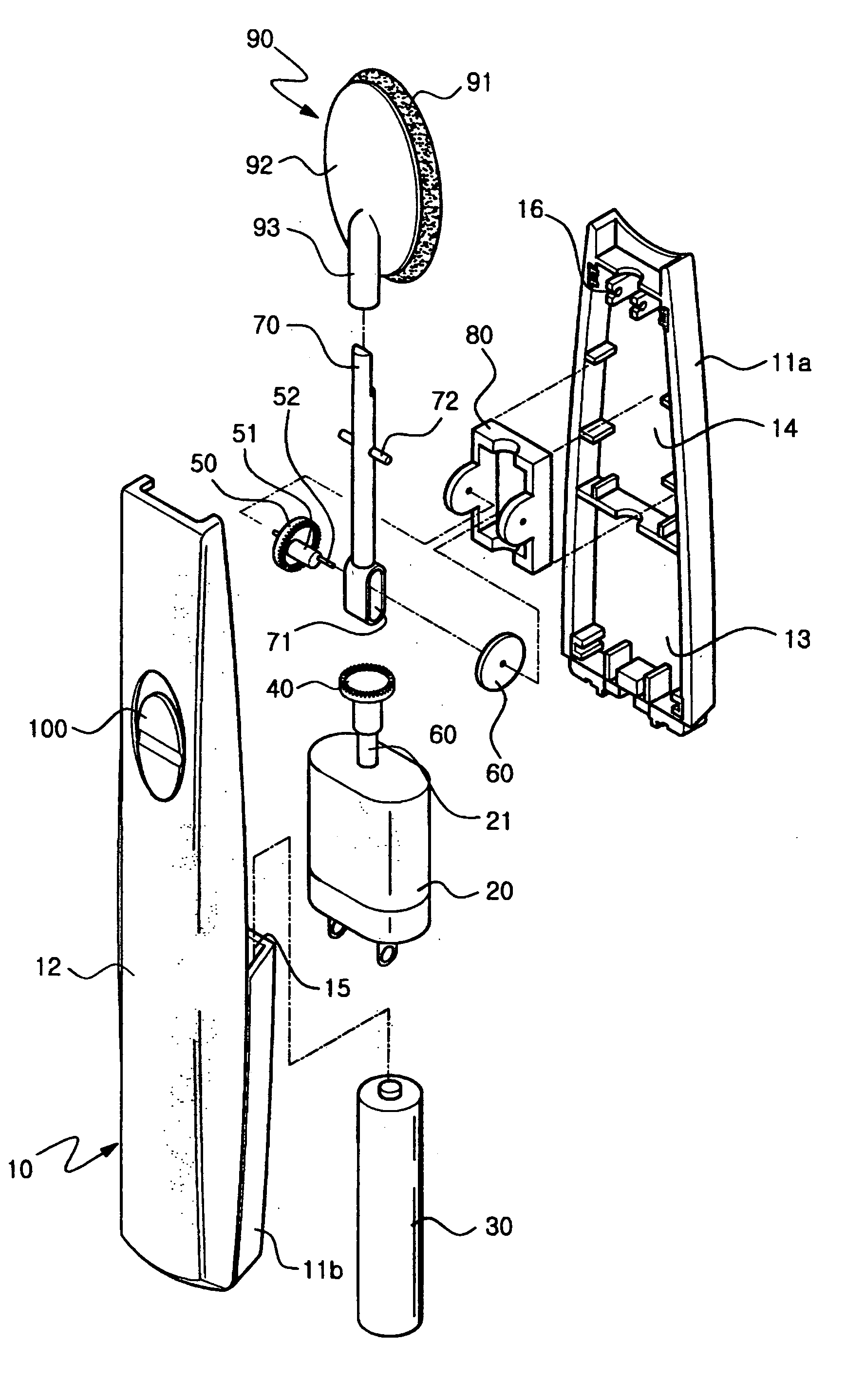
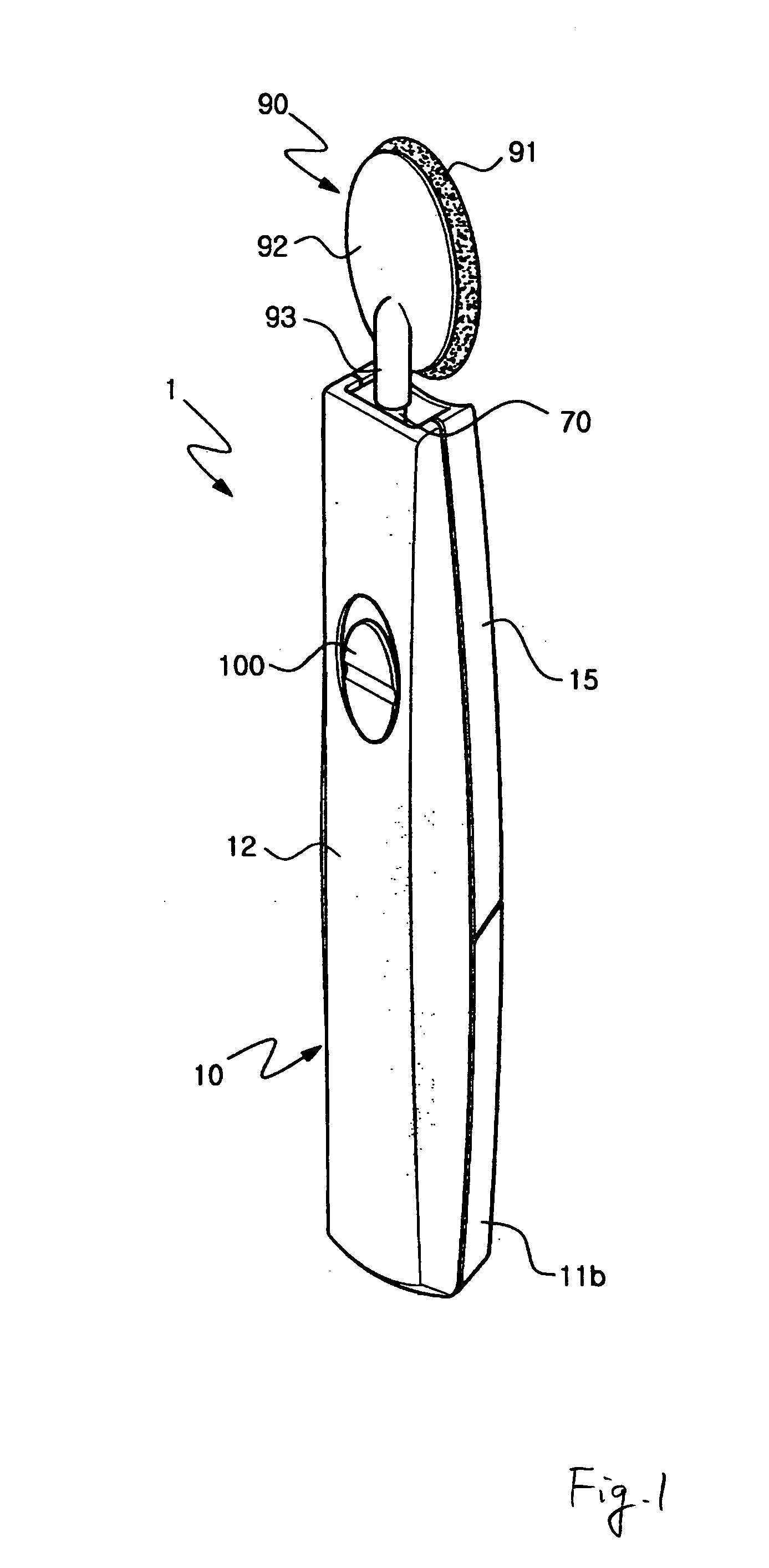
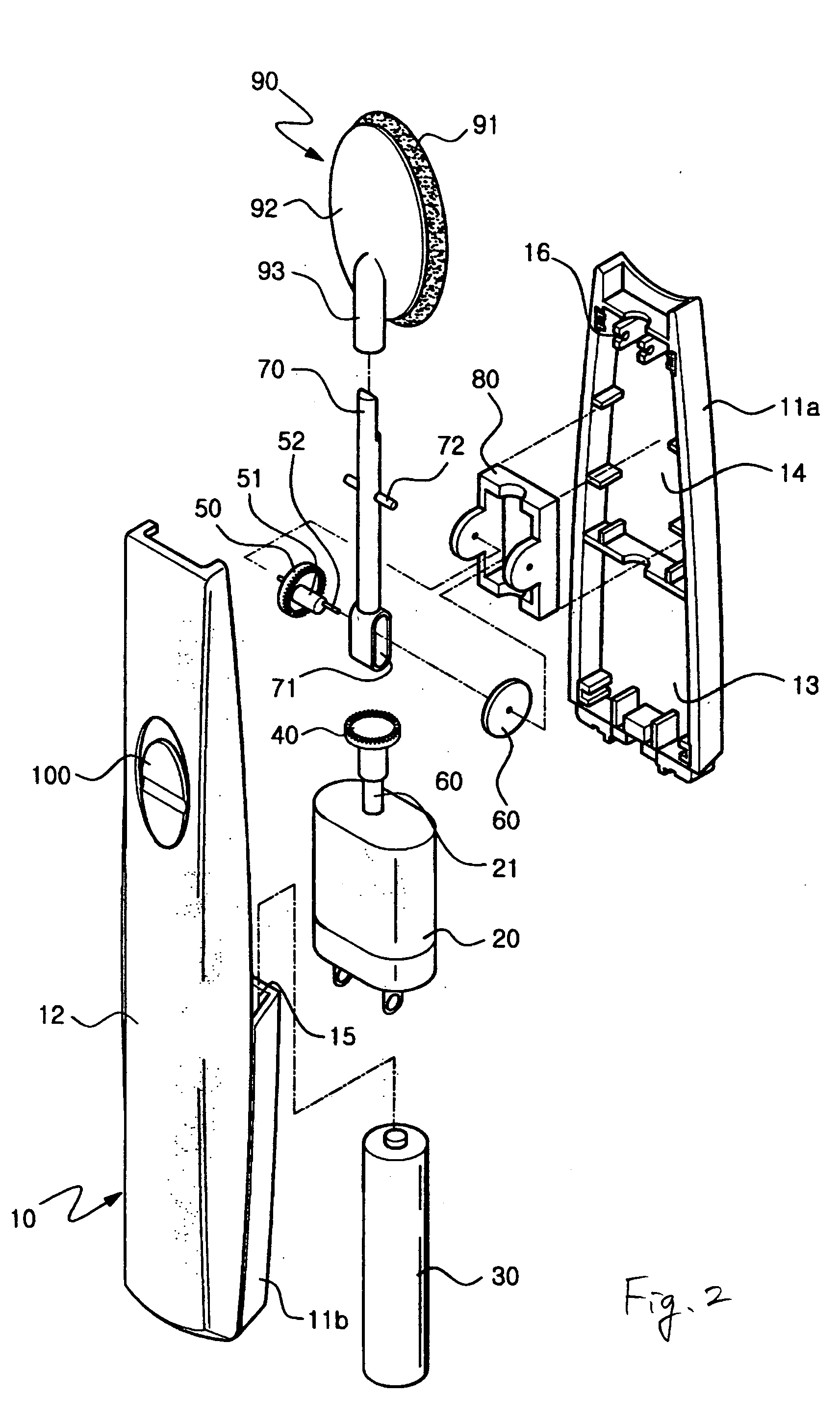
[0029] In the first embodiment constructed as described above, a user couples the puff head 90 to an upper end of the actuating shaft 70 which projects out of the top of the casing 10. Next, the user grips the casing 10 with one hand, and holds the puff plate 91 of the puff head 90 covered with a cosmetic, near a desired body part, especially the face. In such a state, when the electric motor 20 is operated by the power switch 100, the puff plate 91 reciprocates forward and backward, and touches the desired body part with a predetermined force, thus allowing the user to easily put on makeup.

[0030] When electricity is applied to the electric motor 20 to rotate the rotating shaft 21 and the drive gear 40, a rotating force of the drive gear 40 is transmitted to the conversion gear 50. Thus, the cam shaft 51 rotates along with the conversion gear 50. At this time, the actuating shaft 70 coupled to the cam shaft 51 through the longitudinal hole 71 swings while being supported by the supp...

second embodiment

[0032]FIGS. 4 and 5 show the present invention.

[0033] A puff plate 91 is attached to a head part 92 of a puff head 90 with a connection pipe 93.

[0034] An actuating shaft 70 is detachably coupled to the connection pipe 93, and is swung while being supported by support pins 72.

[0035] A groove 102 is provided at a lower end of the actuating shaft 70.

[0036] Further, an eccentric unit is provided between the groove 102 and a rotating shaft 21, and is eccentrically rotated by an electric motor 20 to change the rotating movement of the rotating shaft 21 into the linear movement of the actuating shaft 70, thus oscillating the puff plate 91 forward and backward.

[0037] The eccentric unit includes a shaft support part 103 to support the rotating shaft 21 of the electric motor 20, and an eccentric shaft 104.

[0038] The eccentric shaft 104 is provided on the shaft support part 103 and eccentrically rotated by a drive force of the electric motor 20 transmitted to the shaft support part 103 wh...


PUM


Abstract

Disclosed herein is an electric puff, intended to rapidly and easily apply various types of cosmetics to a desired body part. A conventional puff is problematic in that a user must dab a surface covered with a cosmetic on a desired body part by hand, so that it is very complicated to do a user's makeup, and besides, it is difficult to keep a user's force constant, so that the cosmetic may not be evenly applied to the desired body part. The electric puff of this invention is constructed so that an actuating shaft is swingably coupled to an electric motor installed in a handle-shaped casing via a drive gear and a conversion gear and a puff head is coupled to an upper end of the actuating shaft, thus allowing a cosmetic to be evenly applied to a desired body part with a constant force although a user does not reciprocate the puff by hand, therefore allowing the user to rapidly and easily put on makeup, and allowing the cosmetic to be effectively applied to the desired body part.

Description

BACKGROUND OF THE INVENTION [0001] 1. Field of the Invention [0002] The present invention relates generally to electric puffs, intended to rapidly and easily apply various types of cosmetics, including powder, gel, facial cream, etc., to a desired body part, especially the face, and more particularly, to an electric puff which is constructed so that a rotating shaft of an electric motor installed in a casing is coupled to an actuating shaft connected to a puff plate, via a conversion means, thus oscillating the puff plate forward and backward when the electric motor is driven. [0003] 2. Description of the Related Art [0004] As well known to people, a user applies a cosmetic to a desired body part, especially the face, with the user's hand or various kinds of makeup tools, such as a brush, a pencil, a puff, etc. Particularly, when a user evenly applies makeup powder, including foundation, to a desired body part, a small plate-shaped puff is usually used. [0005] The puff has a shape o...

Claims


Application Information

Patent Timeline
IPC IPC(8): A45D33/34A45D33/36A45D34/04
CPCA45D33/36A45D2200/1018A45D34/04A45D33/34A45D40/26
Inventor CHOO, YOON JEONG
Owner CHOO YOON JEONG
Learn More