Tree follower

a follower and tree technology, applied in the field of follower, can solve the problems of damage or breakage of branches, poor positioning of shakers, adverse effects on harvesting, etc., and achieve the effect of reducing the number of adjustments

a follower and tree technology, applied in the field of follower, can solve the problems of damage or breakage of branches, poor positioning of shakers, adverse effects on harvesting, etc., and achieve the effect of reducing the number of adjustments

US20060021319A1Inactive Publication Date: 2006-02-02OXBO INT CORP

Image

  • Tree follower
  • Tree follower
  • Tree follower

Examples


Embodiment Construction

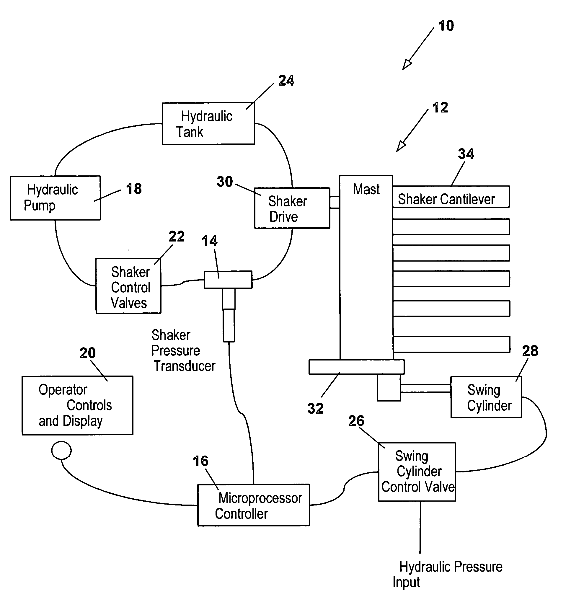
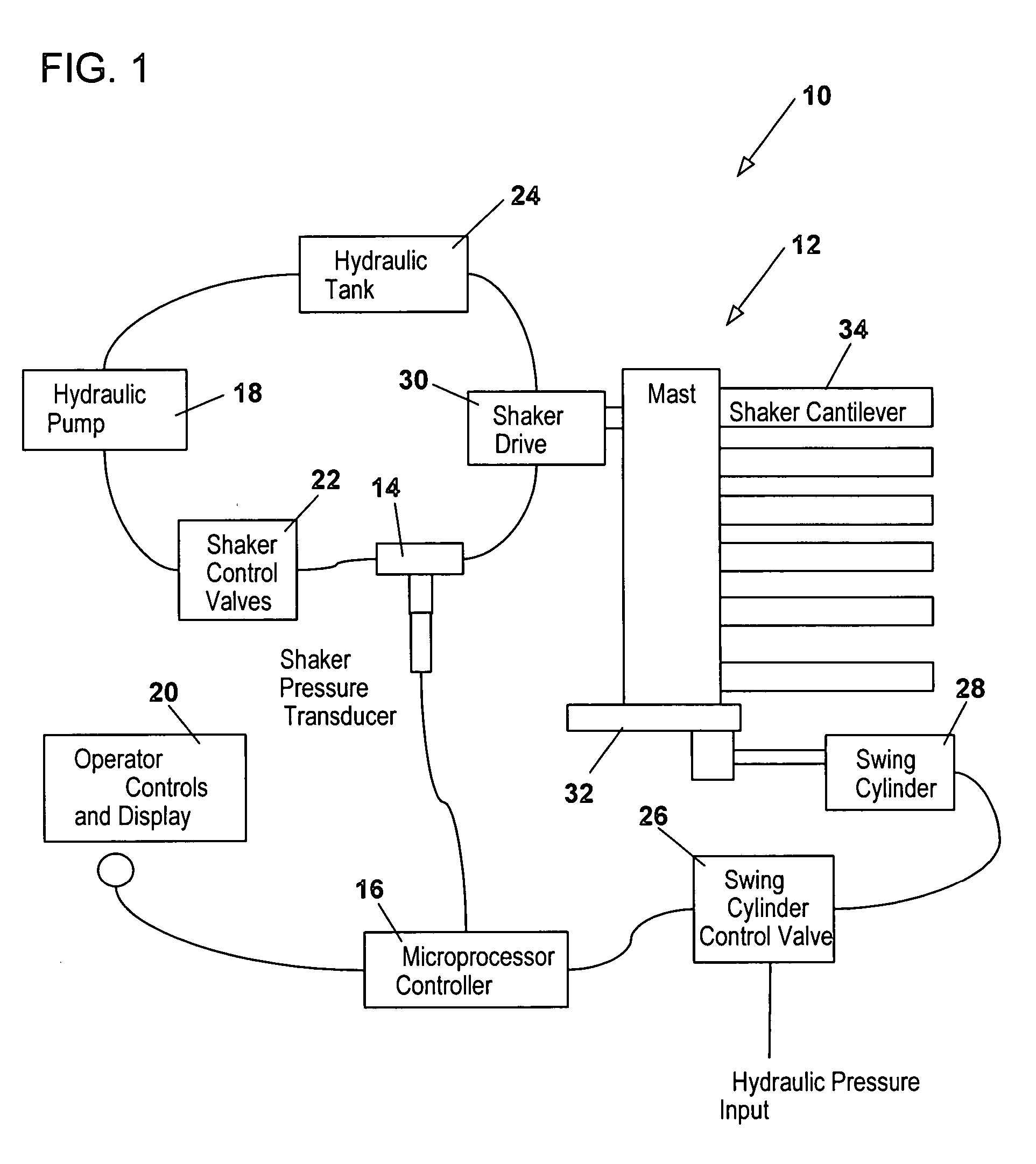
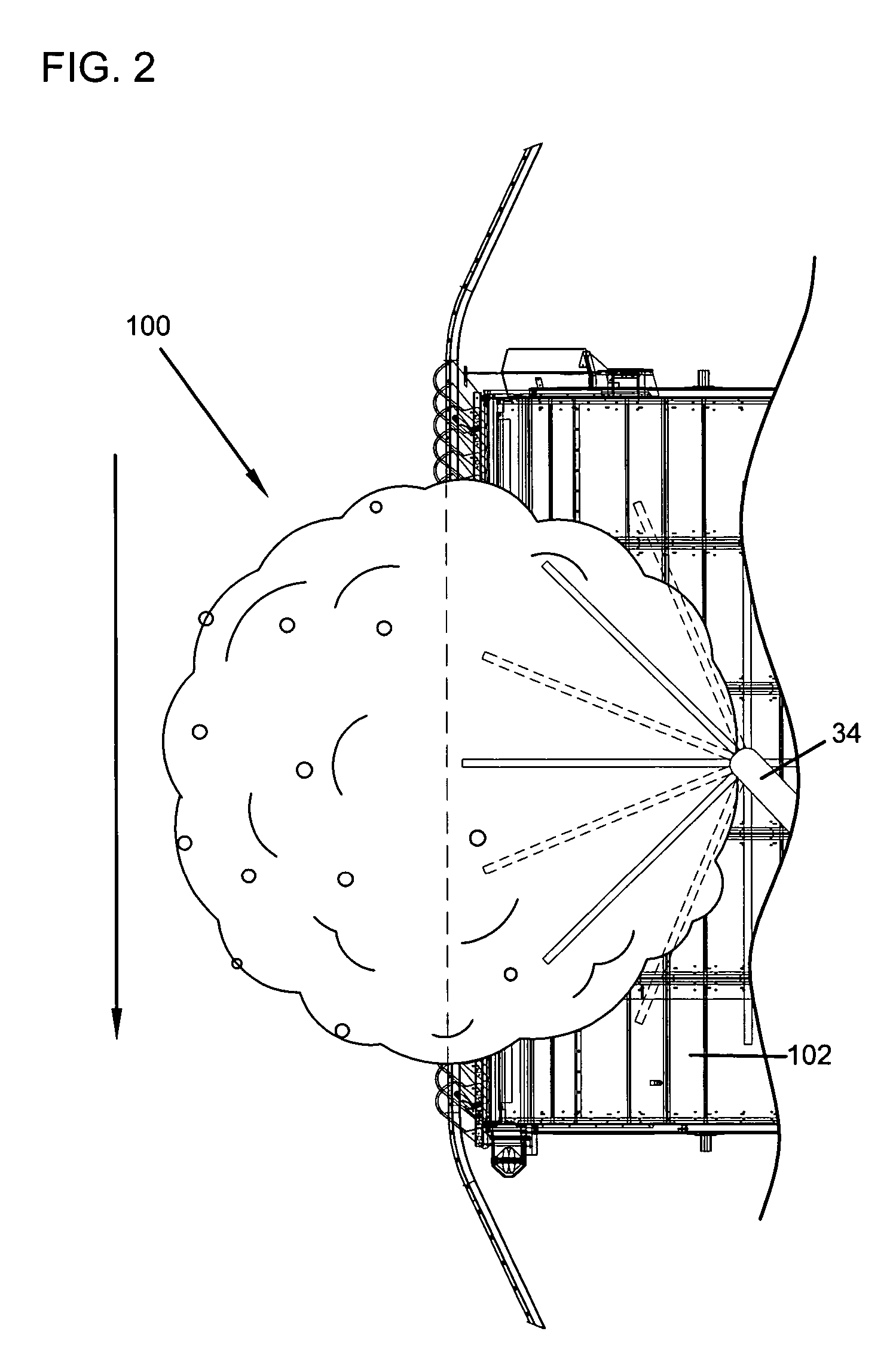
[0020] Referring now to the drawings, wherein like reference letters and numerals indicate corresponding structure throughout the several views and in particular to FIG. 1, there is shown a tree follower system, generally designated 10. The follower system 10 may be utilized on a harvester device, generally designated 100 and shown in FIG. 2. Such harvester devices are well known. An example of a citrus harvester is shown in U.S. Pat. No. 6,463,725 to Briesemeister, incorporated herein by reference.

[0021] The harvester 100 generally includes a conveyor 102 mounted on a frame 106. A cab 104 near the rear of the harvester 100 generally includes a controller 16 for the tree follower system 10. The conveyor 102 can be moved laterally inward or outward to generally follow the trunk of the tree and a trunk seal forms a nearly continuous catch surface when the harvesters 100 are used in pairs, so that a large percentage of the loosened fruit is caught and very little fruit falls to the gr...


PUM


Abstract

The present invention is directed to a tree follower device. The tree follower device includes an engagement assembly that penetrates into and shakes the branches of fruit trees to dislodge the fruit. A pressure transducer in communication with a controller measures the pressure resistance from engagement with the branches and moves the tree follower device further into and out of the branches depending upon the resistance. The present invention allows for programming various upper and lower limits and for operating in different modes for different types of trees. The present invention also provides for varying the sensitivity and the speed at which the engagement devices moves into or out of the tree.

Description

BACKGROUND OF THE INVENTION [0001] 1. Field of the Invention [0002] The present invention relates to a tree follower system and in particular, to a tree follower such as may be used with devices for harvesting fruits and nuts from trees. [0003] 2. Description of the Prior Art [0004] Devices for engaging trees and harvesting fruit and nuts are well known. Such devices have shaker assemblies with whorl arrangements that extend into the tree branches and shake the branches to loosen fruit. Examples of such harvester devices are shown in U.S. Pat. No. 6,463,725 to Briesemeister, and U.S. Pat. No. 6,178,730 to Visser. Although such devices have an extendible conveyor and form a seal with the trunk of the tree, following the shape of the branches with the shaker is controlled by the operator driving the harvester device. Although the position can be controlled and there is some flexure from the arrangements engaging the tree branches, positioning of the shaker is often not optimized. If t...

Claims


Application Information

Patent Timeline
02 Feb 2006
Publication
US20060021319A1
IPC
A01D46/00
CPC
A01D46/28
Inventors
RUSSELL, ALLEN E.; OZMINKOWSKI, TIMOTHY J.