Air/fuel ratio control system for automotive vehicle using feedback control

a technology of air/fuel ratio and feedback control, which is applied in the direction of electrical control, machine/engine, exhaust treatment electric control, etc., can solve the problems of deterioration of emissions, lack of control response rate, and complexity of system structure, so as to reduce the harmful emission reduction efficiency and reduce the weighting factor. , the effect of reducing the weighting factor

US20060021325A1Inactive Publication Date: 2006-02-02DENSO CORP
9 Cites 17 Cited by

Patent Information

Authority / Receiving Office
US · United States
Patent Type
Applications(United States)
Current Assignee / Owner
Publication Date
2006-02-02
Estimated Expiration
Not applicable · inactive patent

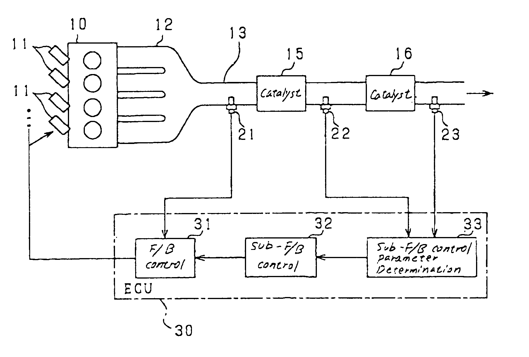
Smart Images

  • Figure 1
    Figure 1
  • Figure 2
    Figure 2
  • Figure 3
    Figure 3
Patent Text Reader

Abstract

An simplified structure of an air-fuel ratio control system for an internal combustion engine includes an upstream and a downstream catalytic device installed in an exhaust pipe of the engine and a first, a second, and a third air-fuel ratio sensor installed in upstream or downstream side of the exhaust pipe. The system also includes a first feedback controller working to bring a value of the air-fuel ratio, as measured by the first air-fuel ratio sensor, into agreement with a target one and a second feedback controller working to sample values of the air-fuel ratios, as measured by the second and third air-fuel ratio sensors, to correct a predetermined controlled parameter in the feedback control of the first feedback controller.
Need to check novelty before this filing date? Find Prior Art

Description

CROSS REFERENCE TO RELATED DOCUMENT

[0001] The present application claims the benefit of Japanese Patent Application No. 2003-432627 filed on Dec. 26, 2003, the disclosure of which is incorporated herein by reference. BACKGROUND OF THE INVENTION

[0002] 1. Technical Field of the Invention

[0003] The present invention relates generally to an air-fuel ratio control system for internal combustion engines, and more particularly to such a system designed to perform feedback control on an air-fuel ratio of the engine using outputs of air-fuel ratio sensors.

[0004] 2. Background Art

[0005] There are known air-fuel ratio control systems for internal combustion engines which have air-fuel ratio sensors installed upstream and downstream of an exhaust emission control catalytic device disposed in an exhaust pipe of the engine and use outputs of the air-fuel ratio sensors to control the air-fuel ratio of the engine for enhancing the emission control. For example, Japanese Patent First Publicatio...

Examples

Embodiment Construction

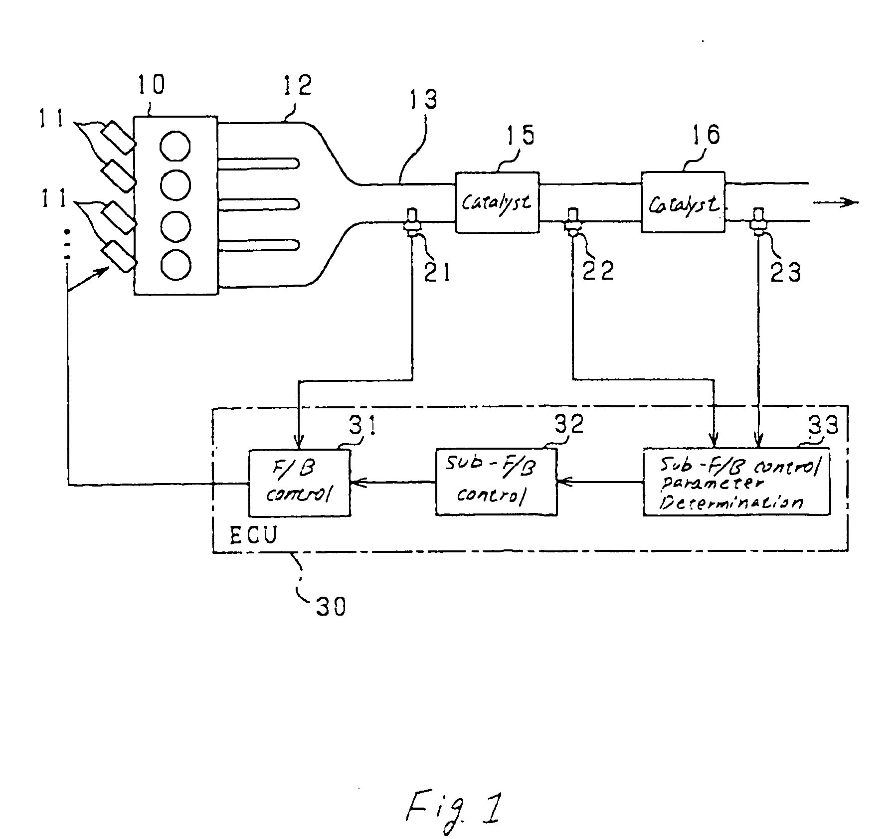
[0026] Referring to the drawings, particularly to FIG. 1, there is shown an engine control system for internal combustion engines according to the invention.

[0027] The engine control system, as illustrated, is designed for a four-cylinder gasoline engine 10 (i.e., a multi-cylinder internal combustion engine) and works to perform an air-fuel ratio control function, as will be discussed later in detail. The engine control system includes an engine electronic control unit 30 (will also be referred to as engine ECU below) which works to control the quantity of fuel to be injected into the engine 10 and the ignition timing of the fuel.

[0028] The engine 10 has solenoid-operated fuel injectors 11 (also called electromagnetic injectors) one for each cylinder. The fuel injectors 11 are installed near intake ports of the engine 10. When the fuel is injected from each of the fuel injectors 11 into a corresponding one of combustion chambers of the engine 10, it creates a mixture of sucked air...