Charge loss detection and prognostics for multi-modular split systems

a multi-modular split and charge technology, applied in the direction of instruments, heat measurement, lighting and heating apparatus, etc., can solve the problems of hvac system components that fail before the time of the hvac system, slow rate, and typical loss of refrigeran

Inactive Publication Date: 2006-02-02
CARRIER CORP
View PDF19 Cites 107 Cited by
  • Summary
  • Abstract
  • Description
  • Claims
  • Application Information

AI Technical Summary

Benefits of technology

[0012] This invention also includes a method of determining the level of refrigerant charge using principal component analysis. Simulations are performed for different operating conditions at full and low refrigerant charges. The difference between a sing

Problems solved by technology

Loss of refrigerant can result in premature failure of HVAC system components.
Loss of refrigerant typically occurs over time and at a very slow rate.
Known systems for detecting refrigerant loss are capable of detecting a significant loss in refrigerant such that the HVAC no longer functions optimally.
However such systems only measure current refrigerant levels, and do not predict future levels of refrigerant to prevent a system from reaching a level where the loss of refrigerant requires immediate attention.
The use of additional sensors is costly, ad

Method used


Image

  • Charge loss detection and prognostics for multi-modular split systems
  • Charge loss detection and prognostics for multi-modular split systems
  • Charge loss detection and prognostics for multi-modular split systems

Examples


Embodiment Construction

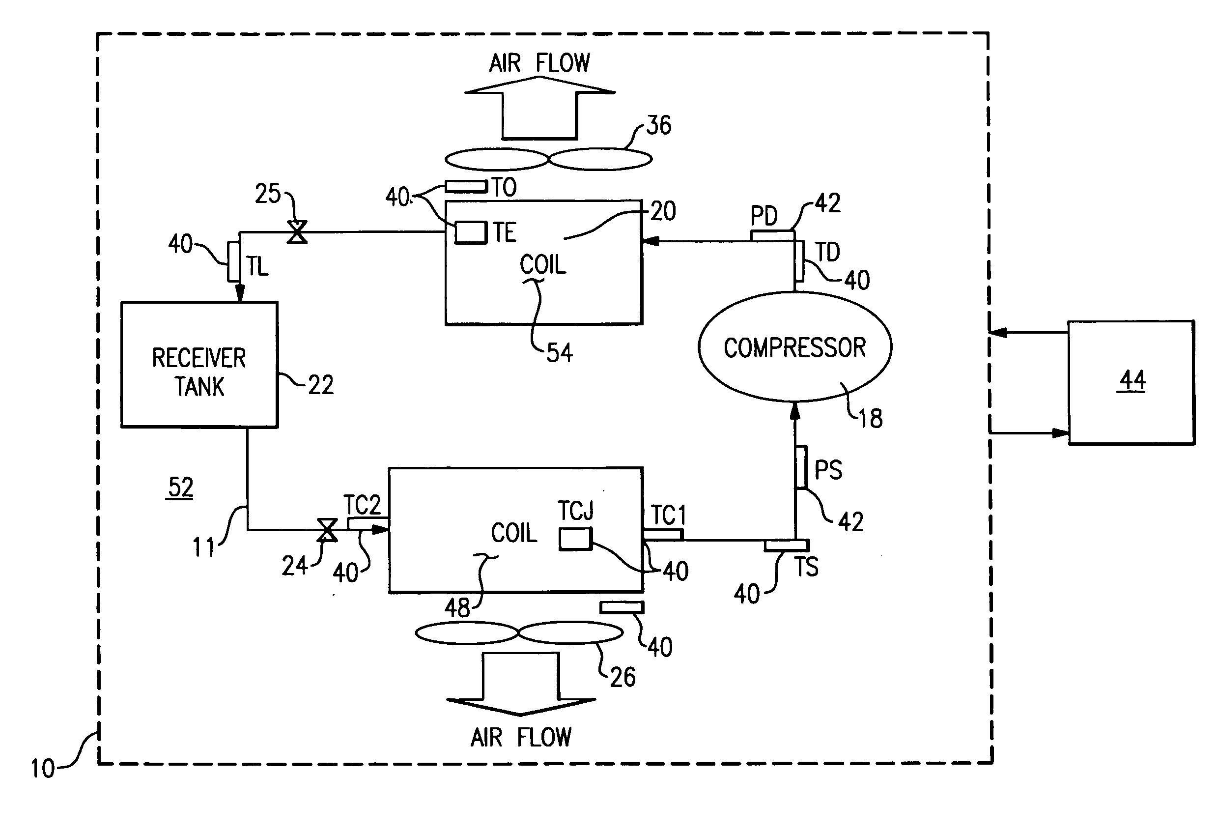
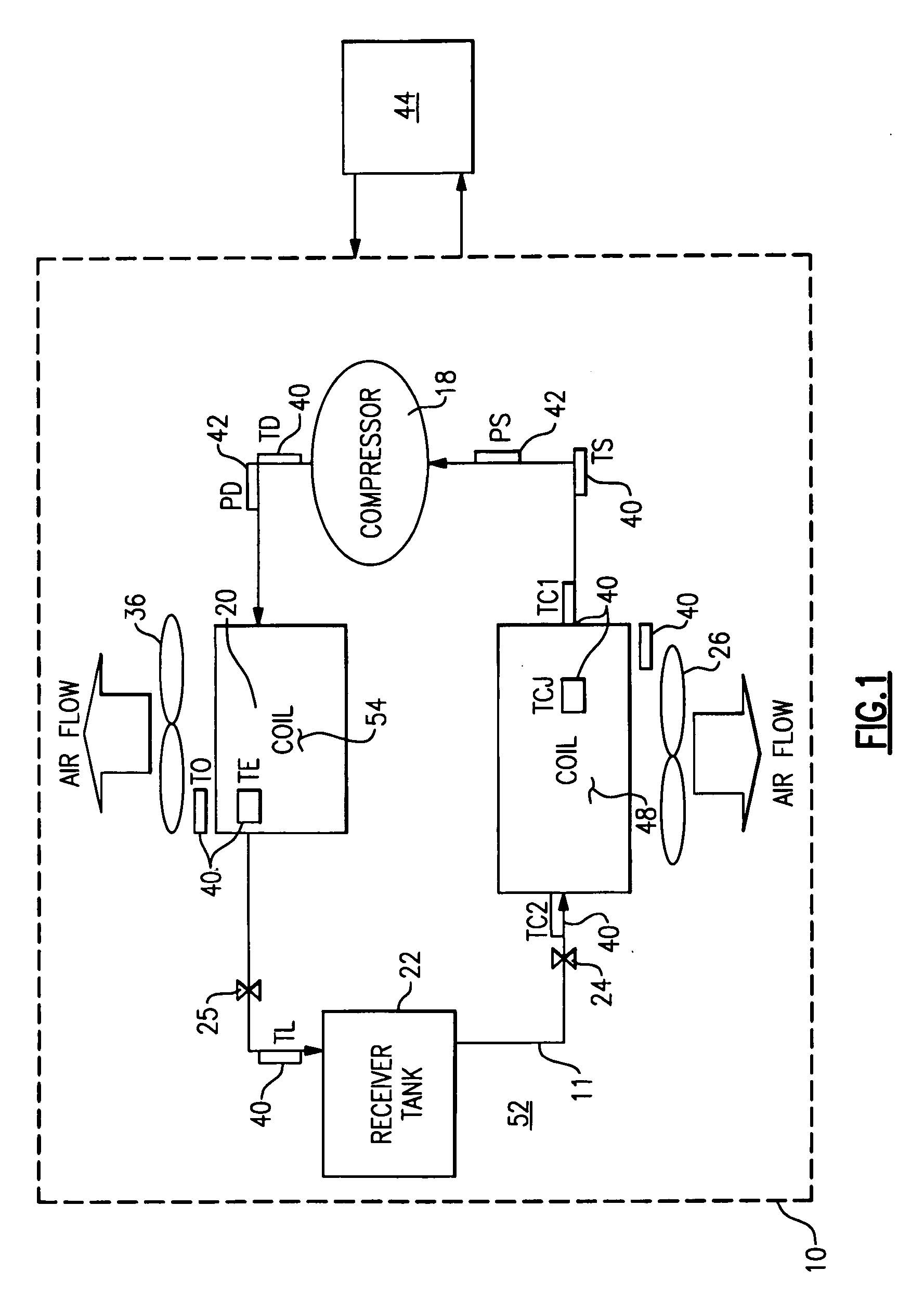
[0021] Referring to FIG. 1, a vapor compression heat pump system 10 includes a first coil 48 and second coil 54. A refrigerant circuit 11 includes a desired amount of refrigerant that flows between the first coil 48 and the second coil 54. The first coil 48 and the second coil 54 are an evaporator and a condenser respectively if the flow of refrigerant is counterclockwise in the refrigerant circuit 11. The first coil 48 and the second coil 54 are a condenser and an evaporator respectively if the flow of refrigerant is clockwise. A compressor 18 compresses air from the evaporator side to the condenser side. A first expansion valve 24 and a second expansion valve 25 control refrigerant flow through the coils 48 and 54. The system 10 includes a liquid reservoir 22 for storing liquid refrigerant. The first coil 48 has a fan 26 and the second coil 54 has a fan 36.

[0022] The system 10 can operate in either a heating mode or a cooling mode depending on the refrigerant flow direction. Spee...


PUM


Abstract

A method for detecting and predicting refrigerant level includes the steps of determining an estimated value for a parameter indicative of refrigerant level and comparing that estimated value to an actual value. The difference between the actual and estimated value provides a refrigerant charge indicator value. The charge indicator value is indicative of the amount of refrigerant contained within the system. A change value is combined with the charge indicator value to provide a prediction for the future value of the charge indicator value. This future value is determined based on a rate of change and charge indicator value over a selected period of time.

Description

BACKGROUND OF THE INVENTION [0001] This invention relates generally to a system for detecting and predicting refrigerant charge levels within a heating ventilating and air conditioning system. [0002] Typically a heating ventilating and air conditioning system (HVAC) includes a refrigerant circuit containing a desired amount of refrigerant. Loss of refrigerant can result in premature failure of HVAC system components. It is therefore desirable to detect and monitor the amount of refrigerant contained within the refrigerant circuit. [0003] Loss of refrigerant typically occurs over time and at a very slow rate. It is desirable to detect the loss of refrigerant and predict a future level of refrigerant in order to optimally schedule maintenance and correction of any problems with the HVAC system. [0004] Known systems for detecting refrigerant loss are capable of detecting a significant loss in refrigerant such that the HVAC no longer functions optimally. However such systems only measur...

Claims


Application Information

Patent Timeline
IPC IPC(8): G01K13/00F25B15/00F25B45/00F25B41/00
CPCF25B49/005F25B2500/19F25B2700/04F25B2600/2513F25B2600/19
Inventor SADEGH, PAYMANFARZAD, MOHSENFINN, ALAN M.KANG, PENGJUSTRICEVIC, SLAVEN
Owner CARRIER CORP
Why Eureka
Try Eureka