Overrunning clutch

a clutch and overrunning technology, applied in the field of overrunning clutches, can solve the problems of excessive internal backlash, limited torque transmitting capacity, and large amount of machining of powered metal components, and achieve the effect of significant reducing backlash and convenient assembly

Inactive Publication Date: 2006-02-02
FORD GLOBAL TECH LLC
View PDF54 Cites 34 Cited by
  • Summary
  • Abstract
  • Description
  • Claims
  • Application Information

AI Technical Summary

Benefits of technology

[0014] The number of notches for a given diameter is greater than other one-way clutches, thereby significantly reducing backlash. The design lends itself to easy assembly due to its configuration. A pocket plate subassembly contains the rockers and a return spring for each rocker. Before its assembly in the clutch, the pocket plate subassembly restricts the ability of each rocker to pivot in the pocket, and the force of the respective return spring prevents the rocker from exiting the pocket laterally by forcing the rocker into contact with its pocket. This arrangement permits the subassembly to be handled and transported prior to its installation in the clutch with the rockers and springs already installed in the pocket plate subassembly.

Problems solved by technology

Rocker and sprag type one-way clutch assemblies can increase the torque capacity for a given package size compared to those of a roller-type clutch, but they are generally limited in torque transmitting capacity by the magnitude of the contact or bearing stresses caused by contact of the rockers or sprags with the races.
The clutches described in the '978 or '245 patents, however, require a significant amount of machining of the components that are formed of powered metal.
Excessive internal backlash, which can produce noise at unacceptable levels, is a potentially problem under certain operating conditions with these clutches.

Method used


Image

  • Overrunning clutch
  • Overrunning clutch
  • Overrunning clutch

Examples


Embodiment Construction

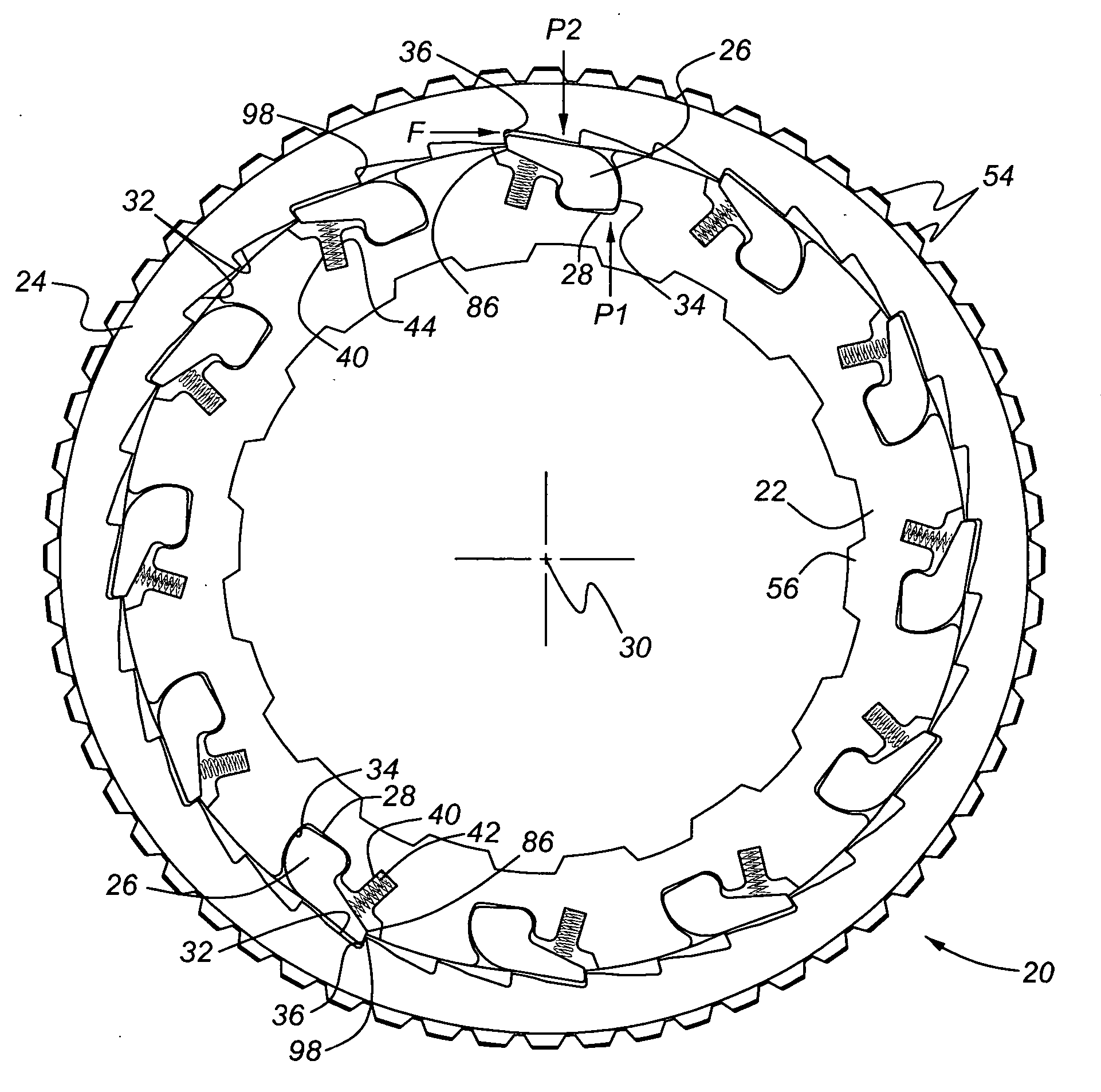
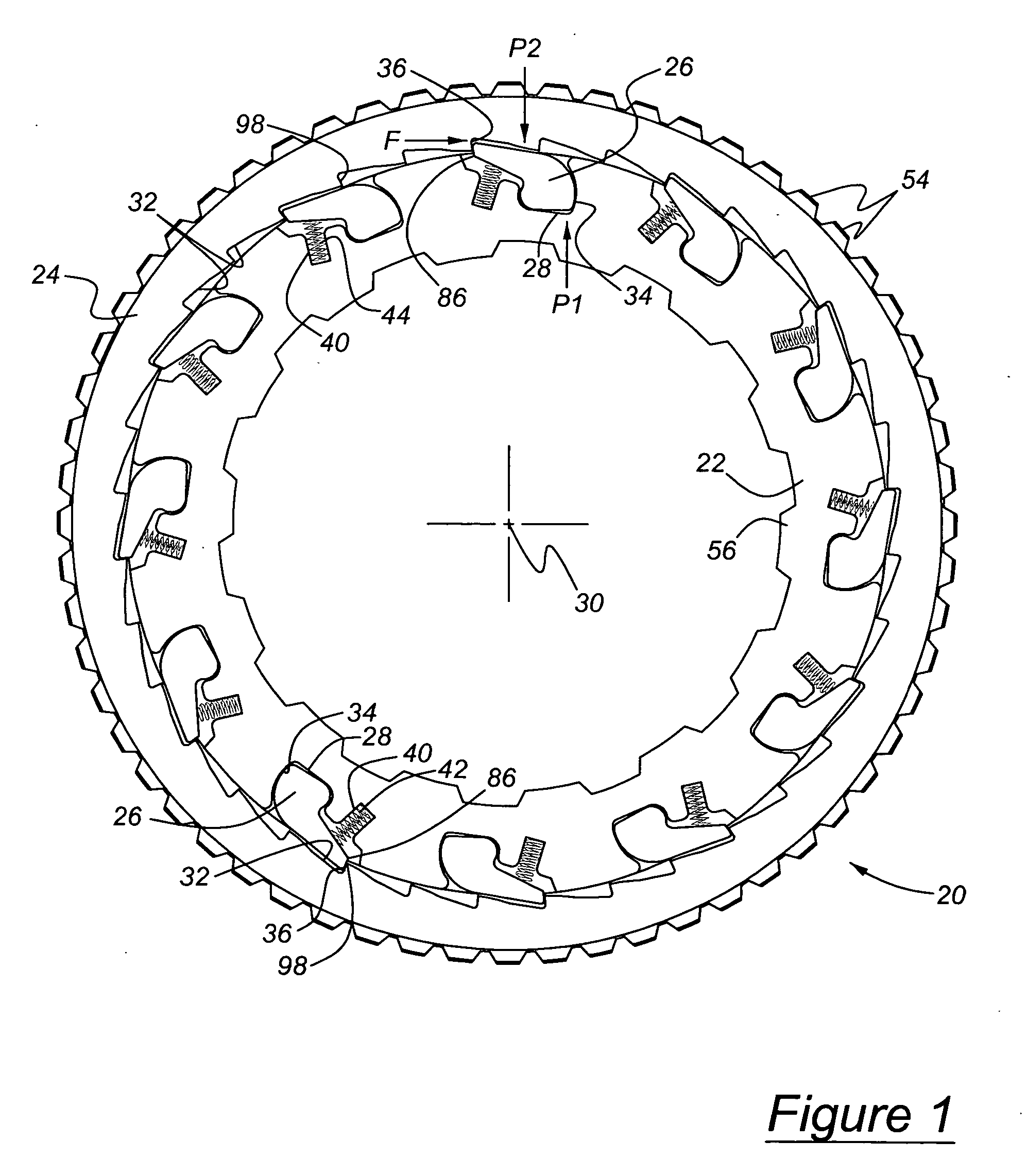
[0030] Referring now to the drawings, there is illustrated in FIG. 1 a one-way clutch assembly 20 in accordance with the present invention. The clutch assembly 20 includes an inner race or rocker plate 22, an outer race or cam plate 24, and a plurality of rockers 26, each rocker being located in a pocket 28 formed in the inner race 22 and angularly spaced mutually about a central axis 30. The inner periphery of the outer race 24 is formed with a plurality of notches 32 angularly spaced mutually about axis 30. There are twelve rockers 26 and pockets 28 and thirty-six notches 32 in the clutch illustrated in FIG. 1.

[0031] When the inner race 22 rotates clockwise faster than the outer race 24, each rocker 26 pivots counterclockwise in its pocket 28 away from engagement with the notches 32 due to contact of the rockers with the inner radial surface of the outer race. This allows the inner race 22 to rotate freely clockwise about axis 30 relative to the outer race 24. When the inner race...


PUM


Abstract

A one-way clutch includes a first race having mutually spaced pockets formed with an opening at a periphery of the first race, each pocket being at least partially bounded by a wall that extends along at least a portion of a margin of the pocket and contains a drive surface. A second race includes a series of alternating notches and cam surfaces formed on a periphery of the second race facing the openings. A plurality of rockers is located in the pockets. Each rocker includes an engagement surface for driveably engaging and disengaging a notch, a reaction surface for contacting the drive surface when the engagement surface driveably engages a notch, and guide surfaces for contacting the pocket wall to guide movement of the rocker from a disengaged position toward an engaged position. Springs, located on the first race, urge the rockers toward engagement with the cam surfaces.

Description

CROSS REFERENCE TO RELATED APPLICATION [0001] This application is a continuation-in-part of pending U.S. application Ser. No. 10 / 899,918, filed Jul. 27, 2004.BACKGROUND OF THE NVENTION [0002] 1. Field of the Invention [0003] The invention relates in general to a clutch that produces a drive connection between components when their relative rotation is in one direction, and overruns when relative rotation is in the opposite direction. In particular, the invention pertains to such clutches having rockers that engage or disengage at least partially due to the effect of centrifugal force acting on the rocker. [0004] 2. Description of the Prior Art [0005] Conventional one-way clutches for producing a one-way drive connection between inner and outer races of the clutch include sprags or rollers for releasably driveably connecting the races and the components of a mechanical assembly connected to the races. Such clutches are commonly used in the powertrain or driveline of an automotive veh...

Claims


Application Information

Patent Timeline
Patent Type & Authority Applications(United States)
IPC IPC(8): F16D41/06
CPCF16D41/12
Inventor KIMES, JOHNSIMON, BERNIEMCDONOUGH, MICHAELLU, XIAOYONG
Owner FORD GLOBAL TECH LLC
Why Eureka
Try Eureka