Pulse frequency modulation for induction charge device

a technology of induction charge and pulse frequency, which is applied in the direction of safety/protection circuit, instruments, transportation and packaging, etc., can solve the problems of power wasting due to power conversion, and devices using contact pads that have already been eliminated

Inactive Publication Date: 2006-02-02
KYE SYST CORP
View PDF8 Cites 303 Cited by
  • Summary
  • Abstract
  • Description
  • Claims
  • Application Information

AI Technical Summary

Benefits of technology

[0009] The present invention has been accomplished under the circumstances in view. It is therefore the main object of the present invention to provide a pulse frequency modulation for induction charge device, which eliminates the aforesaid drawbacks.

Problems solved by technology

Among them, the prior art charge devices used contact pad(s) have already been eliminated gradually due to their bad contacting drawback.
However, the prior par patent does not have ability to detect the load varying, the induction coil continually converting the power when the peripheral charge device need not to be charged, so that causes the power wasting due to power converting.
However, the prior par patent also does not have ability to detect the load varying, the induction coil continually converting the power when the peripheral charge device need not to be charged, so that causes the power wasting due to power converting.
However, it also does not have ability to detect the load varying, the induction coil continually converting the power when the peripheral charge device need not to be charged, so that causes the power wasting due to power converting.
According to the aforesaid description, the contact type charge device has the following drawbacks: (1) the prior art charge devices used contact pad(s) have already been eliminated gradually due to their bad contacting drawback; (2) the charge devices do not have ESD (ESD / electro-static discharge) protecting ability due to the contact pad of the charge devices have been exposed in the air long time.
Furthermore, the aforesaid reaction type charge devices, do not have ability to detect the load varying, the induction coil continually converting the power when the peripheral charge devices need not to be charged, so that causes the power wasting due to power converting.

Method used


Image

  • Pulse frequency modulation for induction charge device
  • Pulse frequency modulation for induction charge device
  • Pulse frequency modulation for induction charge device

Examples


Embodiment Construction

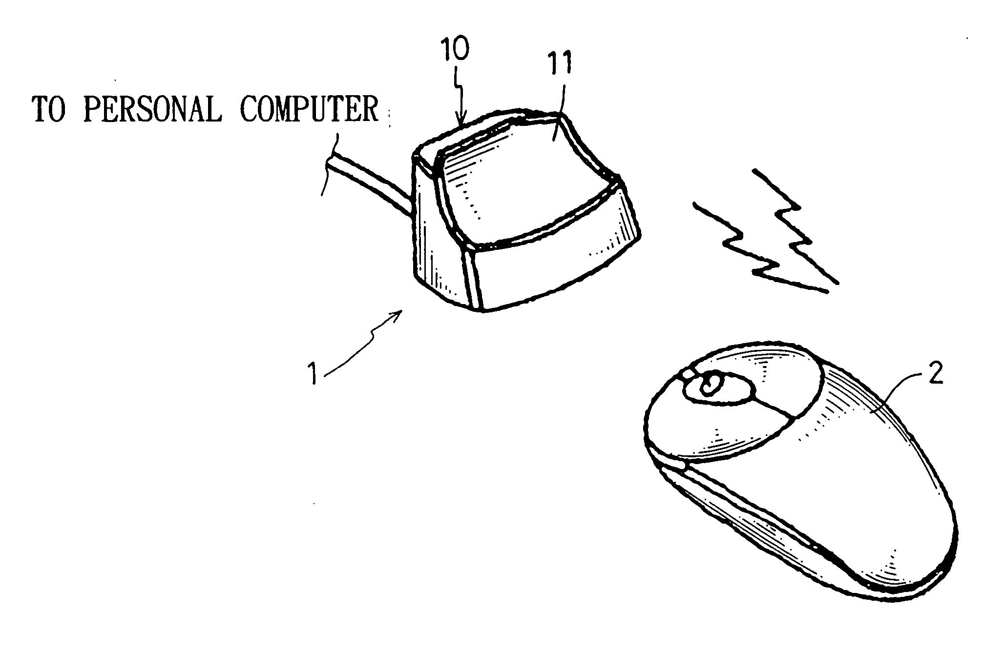
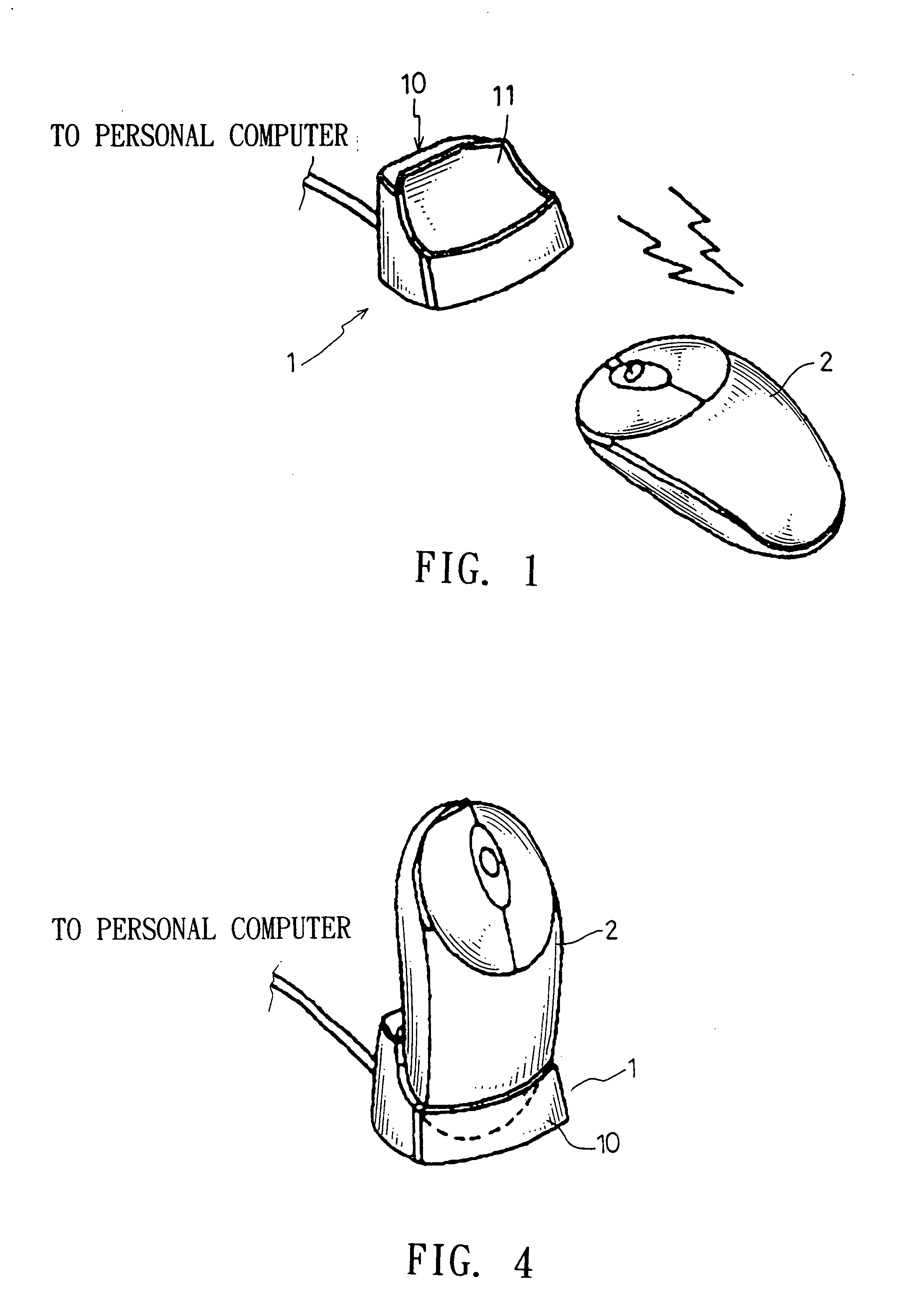
[0019] Referring to FIG. 1, which illustrates a pulse frequency modulation for induction charge device communicating with a portable electronic device by wireless way according to one prefer embodiment of the present invention. As shown in the Fig., the pulse frequency modulation for induction charge device 1 of the present invention comprises: a base seat 10, which comprises a reaction region 11 for positioning the portable electronic device 2 to charge. Wherein, the portable electronic device 2 of the present invention includes but not limited to electronic toothbrush, electronic shaver, etc household appliances, further comprises wireless computer peripheral device, such as wireless mouse, wireless earphone, wireless game controller . . . , etc computer peripheral device. The present invention uses the conventional mouse as an example, wherein the base seat 10 further can integrate a wireless signal receiver to work together.

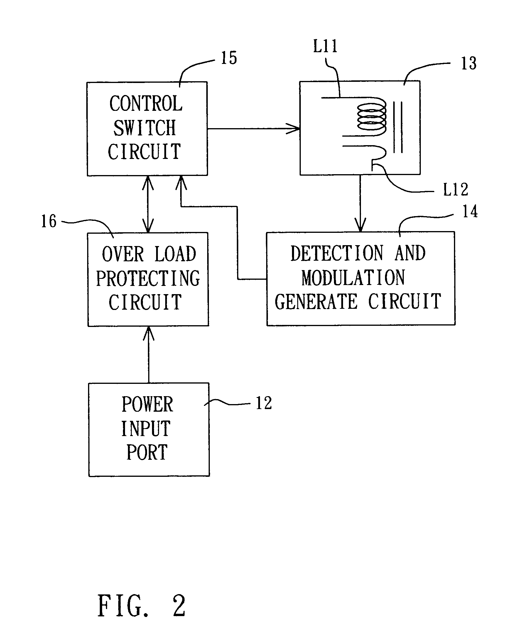
[0020] Referring to FIG. 2, which illustrates a block ...


PUM


Abstract

The present invention is related to a pulse frequency modulation for induction charge device, which comprises a pulse frequency modulation for induction charge device being provided to charge a portable electronic device, wherein, the portable electronic device comprises a induction coil, which comprises: an electric magnetic field generate and the secondary coil react circuit; a detection and modulation generate circuit; and a control switch circuit; whereby, the detection and modulation generate circuit could generate pulse singles with various frequencies according to the load varying generated due to distance varying between the portable electronic device and the charged device, and charge to the portable electronic device according the pulse singles so as to reach the goal of effective management the power.

Description

BACKGROUND OF THE INVENTION [0001] 1. Field of the Invention [0002] The present invention relates to a pulse frequency modulation for induction charge device and, more particularly, relates to a pulse frequency modulation for induction charge device which can generate pulse singles with various frequencies according to the load varying generated due to distance varying between the portable electronic device and the charged device, and charge to the portable electronic device according to the pulse singles so as to reach the goal of effective management the power. [0003] 2. Description of the Related Art [0004] In general, the electronic portable device or computer peripheral device, includes but not limited to electric toothbrush, electric shaver of the general can take reaction type or the peripheral device of computer, include but not confine to electronic toothbrush, shaver . . . , etc home appliances, or wireless computer peripheral device, such as wireless mouse, wireless earph...

Claims


Application Information

Patent Timeline
Patent Type & Authority Applications(United States)
IPC IPC(8): H02J7/00
CPCG06F3/03543H02J7/025G06F3/039G06F3/0383H02J7/00304H02J7/0044H02J50/10
Inventor XIAN, BO-XUNZHENG, REN-KAILU, SHI-HAO
Owner KYE SYST CORP
Why Eureka
Try Eureka