
Power amplifier arrangement and method for memory correction/linearization

a power amplifier and memory correction technology, applied in the field of power amplifiers, can solve the problems of inefficient and wasteful power amplifier arrangement, finite bandwidth of vdd modulator, and inability to always exactly track the envelope of input signal, so as to reduce the complexity of determining programmable parameters and enhance performance.

Active Publication Date: 2006-02-02
APPLE INC
View PDF6 Cites 33 Cited by
  • Summary
  • Abstract
  • Description
  • Claims
  • Application Information

AI Technical Summary

Benefits of technology

[0030] In some embodiments, the training step involves segmenting of a solution space into a plurality of ranges to aid in reducing complexity of determining programmable parameters or to enhance performance.

Problems solved by technology

A conventional power amplifier arrangement having a power amplifier supplied by a static or constant power supply is inefficient and wasteful.
The modulated power supply technique has several drawbacks that have an effect on the linearity of a power amplifier.
Typically, the Vdd modulator has a finite bandwidth and therefore can not always exactly track the envelope of the input signal.
Therefore, proper linearization of the output signal is not achieved and the amplified signal contains distortion if the amplifier has memory.
Linearization correction techniques that are able to address memory impairments typically suffer from additional limitations.
One such limitation is that the techniques begin with the assumption that the distortion is only a function of the input envelope.
Another such limitation is that the techniques are very computationally expensive and require large amounts of memory and / or logic resources that typically grow exponentially with the order of a model used in the technique.

Method used


Image

  • Power amplifier arrangement and method for memory correction/linearization
  • Power amplifier arrangement and method for memory correction/linearization
  • Power amplifier arrangement and method for memory correction/linearization

Examples


Embodiment Construction

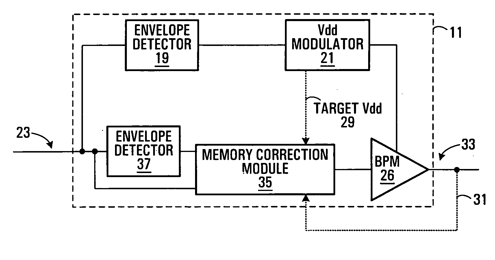
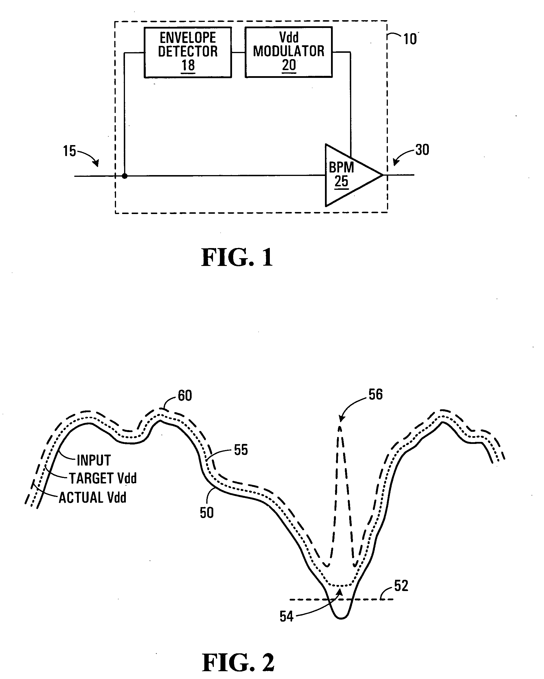
[0050] Referring to FIG. 1, a power amplifier arrangement 10 will be described in detail. The power amplifier arrangement 10 includes an input 15, an output 30, an envelope detector 18, a Vdd modulator 20 and a power amplifier referred to herein as a basic power module (BPM) 25. The input 15 is coupled to the BPM 25. The input 15 is also coupled to the Vdd modulator 20 via the envelope detector 18. The Vdd modulator 20 is a power supply that modulates a power supply signal as a function of the envelope of the signal applied at the input 15. An output of the Vdd modulator 20 is coupled to the amplifier 25. An output of the BPM 25 is coupled to the output 30.

[0051] In operation, a signal is applied to the input 15. The Vdd modulator 20 modulates the power supply signal as a function of the input signal envelope received from the envelope detector 18. The modulated power supply signal is used to power the BPM 25. The BPM 25 amplifies the signal applied to the input 15 of the power amp...


PUM


Abstract

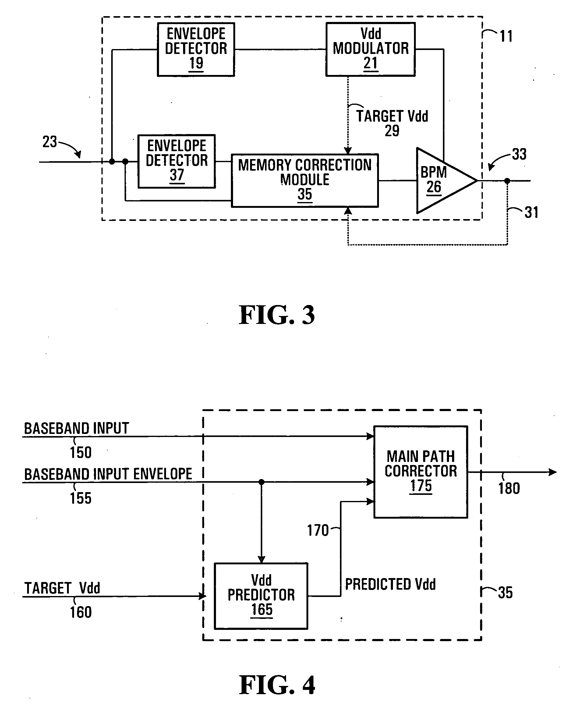
A device, system, and method are provided for a power amplifier arrangement. In embodiments of a Vdd modulated power amplifier arrangement, a memory correction block includes a Vdd predictor for predicting waveform distortions of a Vdd modulated power supply and a main-path corrector for pre-distorting the input to the power amplifier arrangement as a function of the input to the power amplifier arrangement, an input envelope signal determined as a function of the input to the power amplifier arrangement, and an output of the Vdd predictor. Embodiments of the invention provide for operating power amplifier arrangements having memory. In some embodiments, methods of training the Vdd predictor and the main-path corrector of the memory correction block are provided.

Description

FIELD OF THE INVENTION [0001] The invention relates to power amplifiers with modulated power supplies. BACKGROUND OF THE INVENTION [0002] A conventional power amplifier arrangement having a power amplifier supplied by a static or constant power supply is inefficient and wasteful. [0003] One of the current focuses in power amplification design is improved efficiency. Improvements in efficiency lead to a reduced amplifier cost, for example by allowing the use of less expensive transistors with reduced power handling capability, as well as reduced operating expenses resulting from such factors as reduced size, reduced cooling requirements and reduced power requirements. [0004] One method of obtaining improved efficiency is to modulate a power supply of the power amplifier, for example by using a Vdd modulator. In this way, a power supply signal is modulated as a function of an envelope of an input to the power amplifier arrangement. [0005] The modulated power supply technique has sever...

Claims


Application Information

Patent Timeline
IPC IPC(8): H03G3/20
CPCH03F1/0211H03F1/3258H03F2200/102
Inventor FULLER, ARTHURMORRIS, BRADLEY
Owner APPLE INC
Learn More