
Drive sense adjusting apparatus and drive sense adjusting method

Active Publication Date: 2006-02-02
NISSAN MOTOR CO LTD
View PDF16 Cites 56 Cited by
  • Summary
  • Abstract
  • Description
  • Claims
  • Application Information

AI Technical Summary

Benefits of technology

[0004] The present invention has been made in order to solve the above-described problems. It is an object of the present invention to provide a drive sense adjusting apparatus and a drive sense adjusting method, which are capable of adjusting a drive sense of a driver and stabilizing the drive sense of the driver more by presenting a visual stimulus into a vision of the driver.
[0008] According to the drive sense adjusting apparatus and the drive sense adjusting method in accordance with the present invention, visually induced vection can be produced for the driver by the visual stimulus. Accordingly, the drive sense of the driver is adjusted, thus making it possible to stabilize the drive sense of the driver more.
[0009] Moreover, according to the drive sense adjusting apparatus in accordance with the present invention, a direction perpendicular to the screen of the visual stimulus presentation unit and a direction of a displayed image are substantially the same. Accordingly, when the driver visually recognizes the display screen, the image outside of the video, which is displayed on the display screen, and an environment outside of the vehicle, are easily associated with each other, thus making it possible to stabilize the drive sense of the driver.
[0010] Furthermore, according to the drive sense adjusting apparatus in accordance with the present invention, the visual stimulus equivalent to the road optical flow accompanied with the vehicle motion is presented into a peripheral vision of the driver, which is obstructed by functional components of the vehicle in a usual vehicle structure. Accordingly, an area of the entire road optical flow perceived by the driver is increased, thus facilitating for the driver to perceive the heading direction.

Problems solved by technology

However, the speed sense correcting device described above is configured in order to correct a contradiction in the speed sense of the driver, and accordingly, cannot stabilize a drive sense of the driver more by adjusting the drive sense concerned of the driver.
Moreover, the speed sense correcting device described above is one that controls the speed sense of the driver, and accordingly, cannot control drive senses of the driver other than the speed sense, which are such as a heading perception and equilibrium sense of the driver.

Method used


Image

  • Drive sense adjusting apparatus and drive sense adjusting method
  • Drive sense adjusting apparatus and drive sense adjusting method
  • Drive sense adjusting apparatus and drive sense adjusting method

Examples


first embodiment

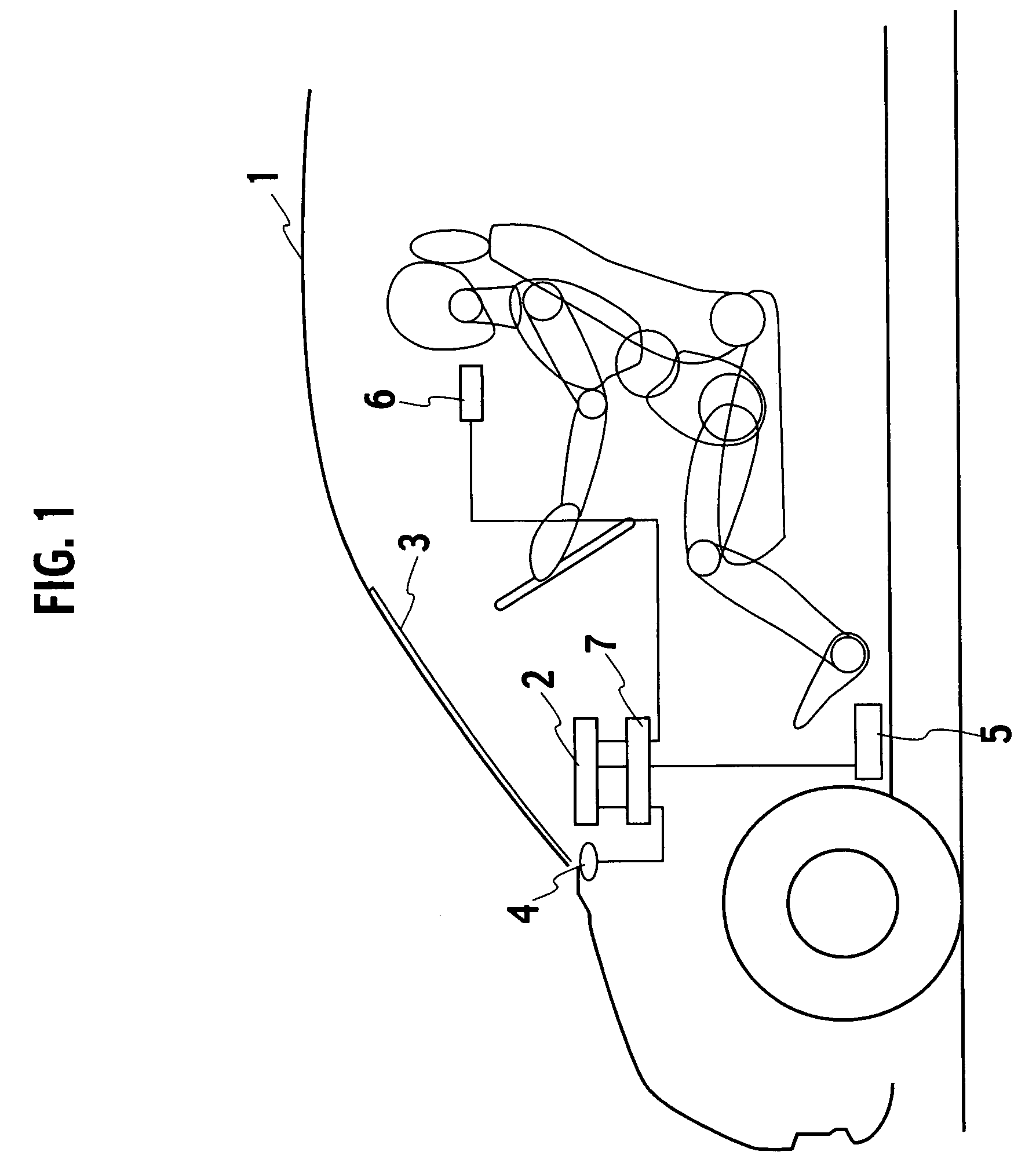
[0062] As shown in FIG. 1, a drive sense adjusting apparatus serving as the present invention includes, as main constituents, a projector 2 mounted on a vehicle 1 and provided on an upper portion of an instrument panel of the vehicle 1, a film 3 formed of a louver-like member, which is adhered on an inner surface of a windscreen glass of the vehicle 1, a driving environment detection unit 4 for detecting a driving environment outside of the vehicle, a vehicle status detection unit 5 for detecting a state quantity of the vehicle 1, a driver status detection unit 6 for detecting a drive state of the driver, and a control unit 7 for controlling visual stimulus presentation processing to be described later.

[0063] The driving environment detection unit 4 detects a scene image, a light quantity and a rainfall quantity outside of the vehicle as information indicating the driving environment outside of the vehicle. Moreover, the vehicle status detection unit 5 detects pitching, rolling, yaw...

second embodiment

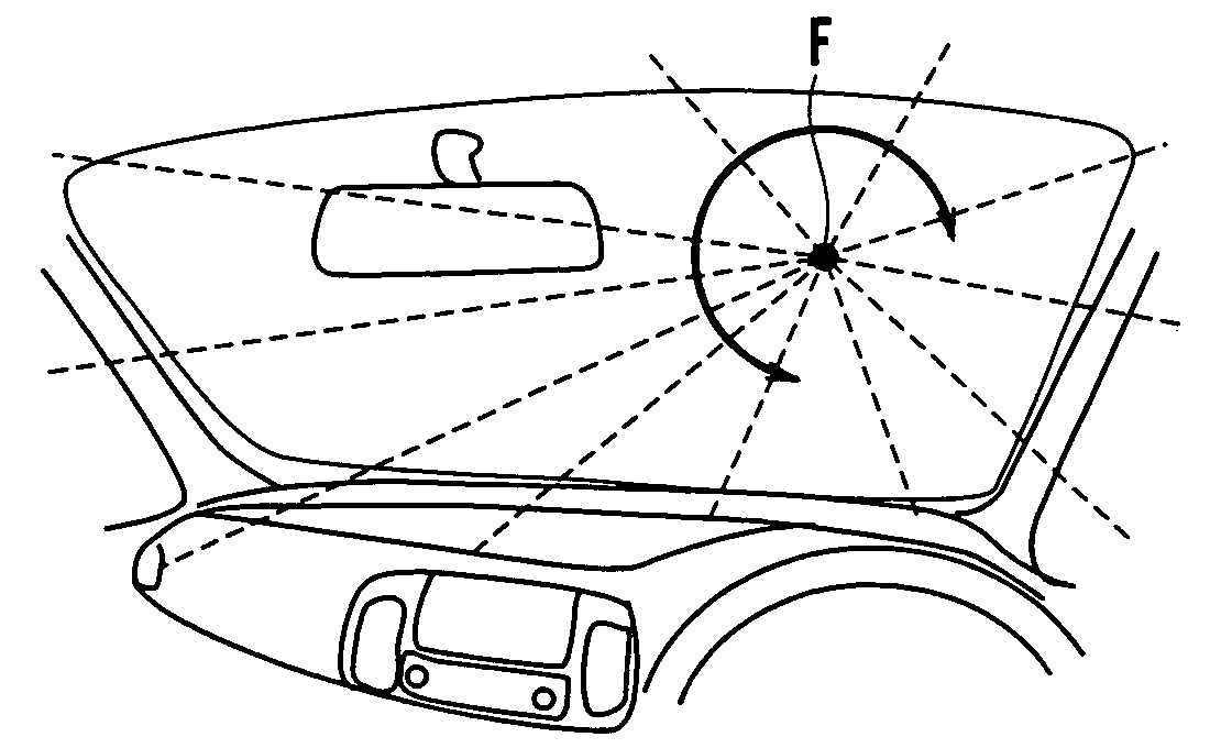
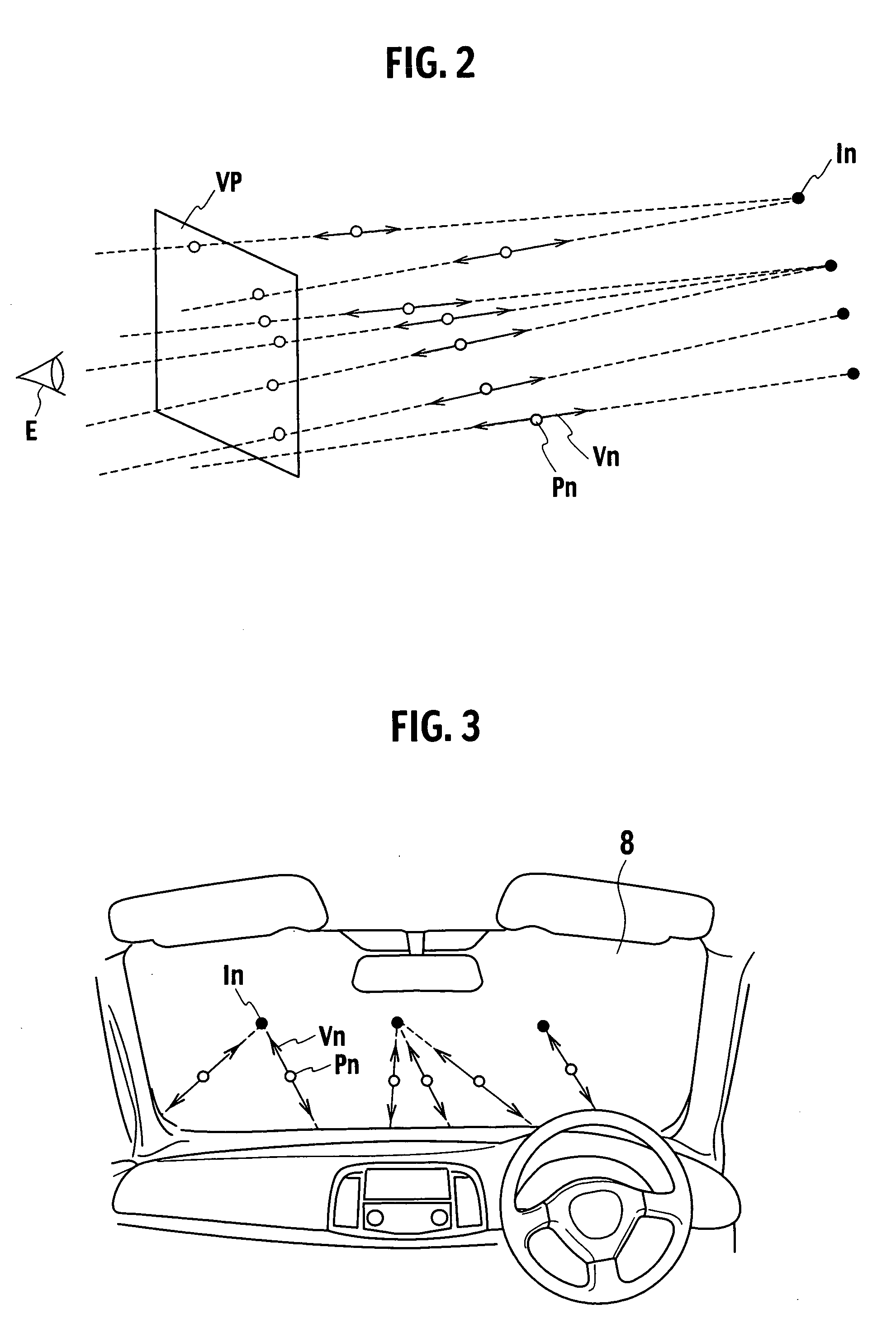
[0082] As apparent from the above description, according to the drive sense adjusting apparatus serving as the present invention, the control unit 7 arranges the plural virtual spots I in the near-field region FR of the focus of expansion F, and presents, as the visual stimulus to the driver, the light spots each of which irregularly repeats occurrence and vanishment or moves in each virtual spot I. Accordingly, in comparison with the case where the visual stimulus is generated from the fixed virtual spot I, the heading perception of the driver can be stably maintained.

[0083] Here, in this embodiment, as shown in FIG. 11, in response to an angle variation of a vector of acceleration about an axis of the vehicle heading direction, the acceleration being applied to the driver or the vehicle 1 at the time of turning, the control unit 7 may rotationally displace the visual stimulus about the focus of expansion F and in the same direction as that of the angle variation of the acceleratio...

sixth embodiment

[0100] As apparent from the above description, according to the drive sense adjusting apparatus serving as the present invention, when the control unit 7 radially divides the virtual plane with the vehicle heading direction taken as the center, and projects the visual stimulus onto the virtual plane VP, the control unit 7 controls the visual stimulus in response to the running direction to be projected on at least one regions radially divided. Accordingly, a visual stimulus more in touch with an actual instance can be presented in response to the outside scene and the drive condition.

[0101] A drive sense adjusting apparatus serving as a seventh embodiment of the present invention has the same configuration as those of the drive sense adjusting apparatuses serving as the first to sixth embodiments. The control unit 7 controls the visual stimulus so that a contrast of an element of the visual stimulus gets weaker as the element approaches the virtual spot (a center position of the vir...


PUM


Abstract

A control unit presents a visual stimulus onto a film adhered on an inner surface of a windscreen glass of a vehicle, and controls the visual stimulus so as to allow a driver to perceive the visual stimulus approaching the driver or receding therefrom in response to detection results of a driving environment detection unit, a vehicle status detection unit and a driver status detection unit. In such a way, visually induced vection can be produced for the driver by the visual stimulus. Accordingly, a drive sense of the driver can be adjusted in response to a vehicle state quantity, a driving environment and a driver state.

Description

BACKGROUND OF THE INVENTION [0001] The present invention relates to a drive sense adjusting apparatus and a drive sense adjusting method, which are for adjusting a drive sense of a driver by presenting a visual stimulus into a vision of the driver. [0002] Heretofore, as disclosed in Japanese Patent Laid-Open Publication No. H11-149272, there has been known a speed sense correcting device for controlling a speed sense of a driver by presenting, as a visual stimulus to the driver, a pattern (reverse-running pattern) moving so as to recede from a vision of the driver. According to such a speed sense correcting device, an incorrect speed sense formed in the driver's brain after high-speed running can be corrected in a short time, and a safe drive can be ensured in a drive that follows. SUMMARY OF THE INVENTION [0003] However, the speed sense correcting device described above is configured in order to correct a contradiction in the speed sense of the driver, and accordingly, cannot stabi...

Claims


Application Information

Patent Timeline
IPC IPC(8): B60Q1/00G08B23/00
CPCG08G1/16B60R1/00G08G1/167
Inventor ITO, MITSUHITOSHIMIZU, YOUJIOKADA, KATSUNORIIWAO, KEIJIROMATSUSHITA, AKIHIROUENUMA, KENYANAKASHIMA, HIROTOHATANO, YOSHIKAZUSUNDA, TAKASHI
Owner NISSAN MOTOR CO LTD
Learn More