Network designing device and program

Inactive Publication Date: 2006-02-02
FUJITSU LTD
View PDF15 Cites 11 Cited by
  • Summary
  • Abstract
  • Description
  • Claims
  • Application Information

AI Technical Summary

Benefits of technology

[0021] Further, according to the first aspect of the invention, the determining unit may be adapted to calculate a Q value indicating characteristics of an optical signal for each assumed path, and determine transmission permission/inhibition based on the Q value. By the adaptation, the user can easily check the transmission permission/inhibition determination based on the Q

Problems solved by technology

However, optical signal characteristics in an optical transmission system are determined by noise light accumulation which accompanies multistage connection of an optical transmission device, and accumulation of complex physical phenomena such as optical fiber wavelength dispersion, polarized wave dispersion, or non-linear effects.
On the other hand, in FIG. 19, since the first to

Method used


Image

  • Network designing device and program
  • Network designing device and program
  • Network designing device and program

Examples


Embodiment Construction

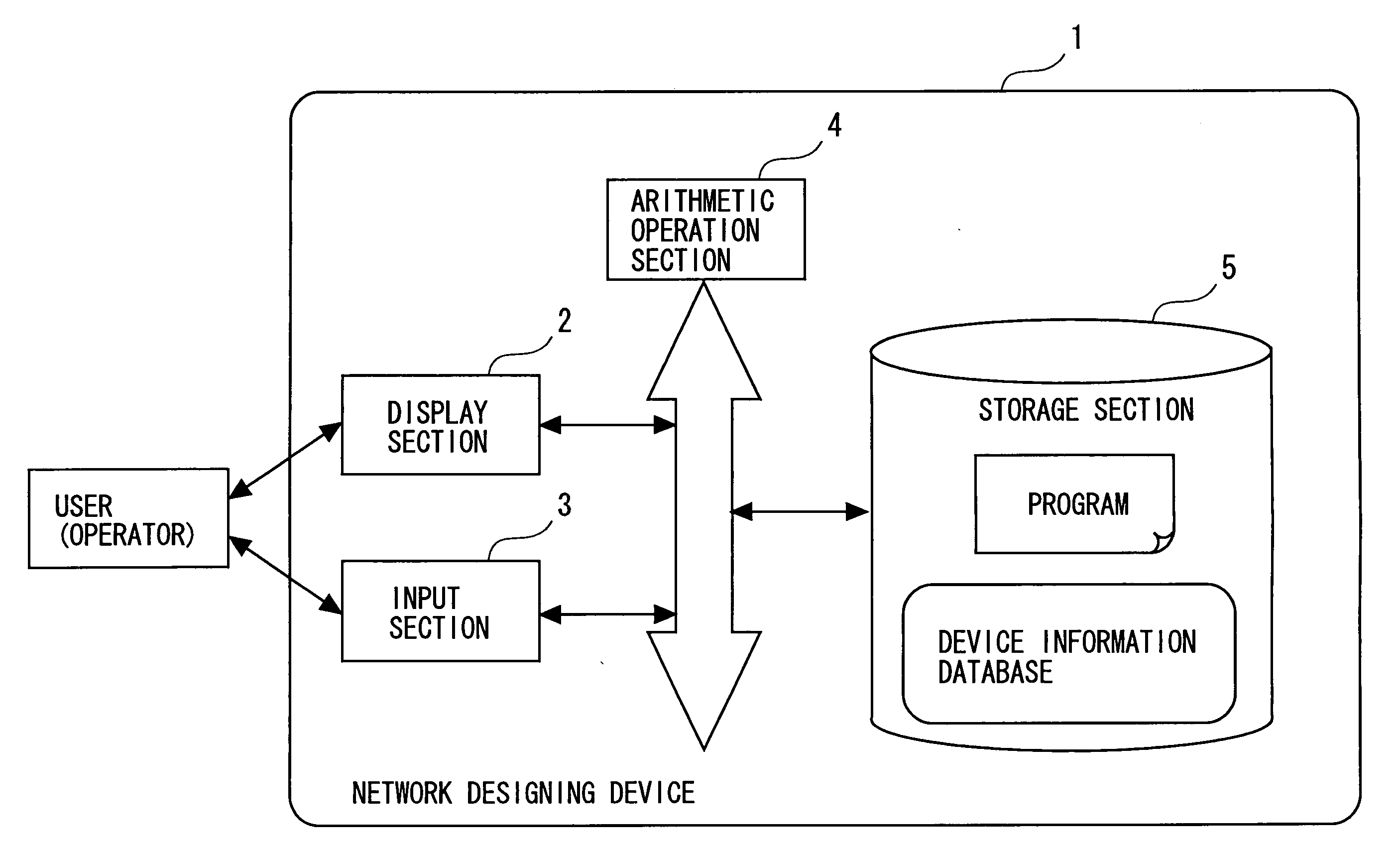
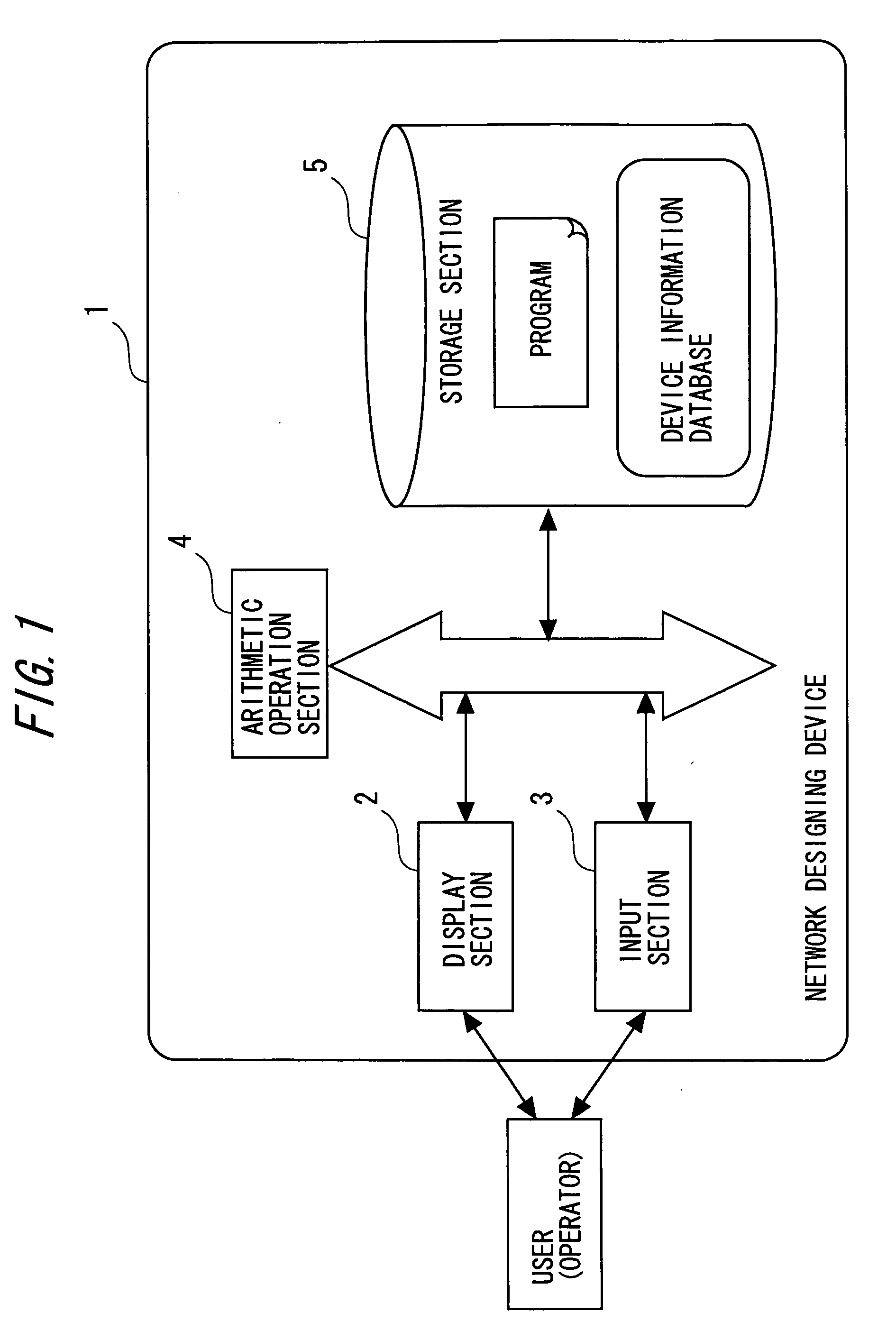
[0046] First, description will be made of a network which is a designing target of a network designing device 1 of the invention. The network to be processed includes a terminal node, a branch node, and a general node. Each node indicates a building. Accordingly, a device to be installed in the building is allocated to each node. In other words, in reality, the device allocated to the node in network designing is arranged in the building.

[0047] The nodes are interconnected via a link. The link indicates a fiber. In other words, in reality, the fiber is installed as the link, and the buildings or the devices therein are interconnected through the fiber to communicate with one another.

[0048] A terminal device is allocated to each terminal node. An HUB is allocated to the branch node. As a result of the network designing, a linear repeater or a regeneration repeater that has a constitution assigned by a user is allocated to the general node.

[0049] Next, a constitutional example of t...


PUM


Abstract

Linear networks are divided into a plurality of regeneration repeating sections which have nodes having regeneration repeaters arranged therein at both ends, devices such as linear repeaters or OADMs are arranged at the nodes positioned in the regeneration repeating sections, a plurality of assumed paths assumed as a result of arranging the devices are extracted in the regeneration repeating sections, and transmission permission/inhibition is determined for each assumed path, and after that, the determined transmission permission/inhibition is displayed to allow a user to perform settings again.

Description

BACKGROUND OF THE INVENTION [0001] The present invention relates to a technology which is effectively applied to a network designing device or a network designing method for supporting optimizing design of an optical communication network. [0002] There is a demand for a technology which enables use of various multimedia services at any time or place. As one of such technologies, a photonic network technology is available, which enables high-speed and inexpensive communication of a large amount of information. Among photonic network technologies, there have been developed a Wavelength Division Multiplexing (WDM) technology which multiplexes and communicates a plurality of optical signals different from one another in wavelength through one optical fiber, and a photonic node technology which constructs a network by regarding each wavelength as one communication path. The development of such technologies has brought about a need to realize a communication network system (hereinafter ca...

Claims


Application Information

Patent Timeline
IPC IPC(8): H04L12/28H04B10/00H04B10/291H04L12/701H04M3/00
CPCH04L41/145
Inventor NAKASHIMA, HISAOHOSHIDA, TAKESHIAKIYAMA, YUICHITERAHARA, TAKAFUMI
Owner FUJITSU LTD
Why Eureka
Try Eureka