Gas turbine rotor

a technology of rotor and gas turbine, which is applied in the direction of marine propulsion, vessel construction, other chemical processes, etc., can solve the problems of reduced service life of the rotor disk and ineffective mechanical sealing, and achieve the effect of enhancing the sealing effect of the latter in a well-controlled manner

Inactive Publication Date: 2006-02-02
ROLLS ROYCE DEUT LTD & CO KG
View PDF15 Cites 7 Cited by
  • Summary
  • Abstract
  • Description
  • Claims
  • Application Information

AI Technical Summary

Benefits of technology

[0008] The airflow can enter the gap axially spaced from the mechanical sealing element or act in combination with the mechanical sealing and damping element and augment the sealing effect of the latter.
[0009] In an ad

Problems solved by technology

With regard to the sealing and damping elements, these gas turbine rotors are disadvantageous in that a single, mechanical seal is not fully effective and will permit hot gas to pass via the gap remaining between the blade platforms into the area beneath the blade platforms and, thus, into the area of fixation of the turbine rotor

Method used


Image

  • Gas turbine rotor
  • Gas turbine rotor
  • Gas turbine rotor

Examples


Embodiment Construction

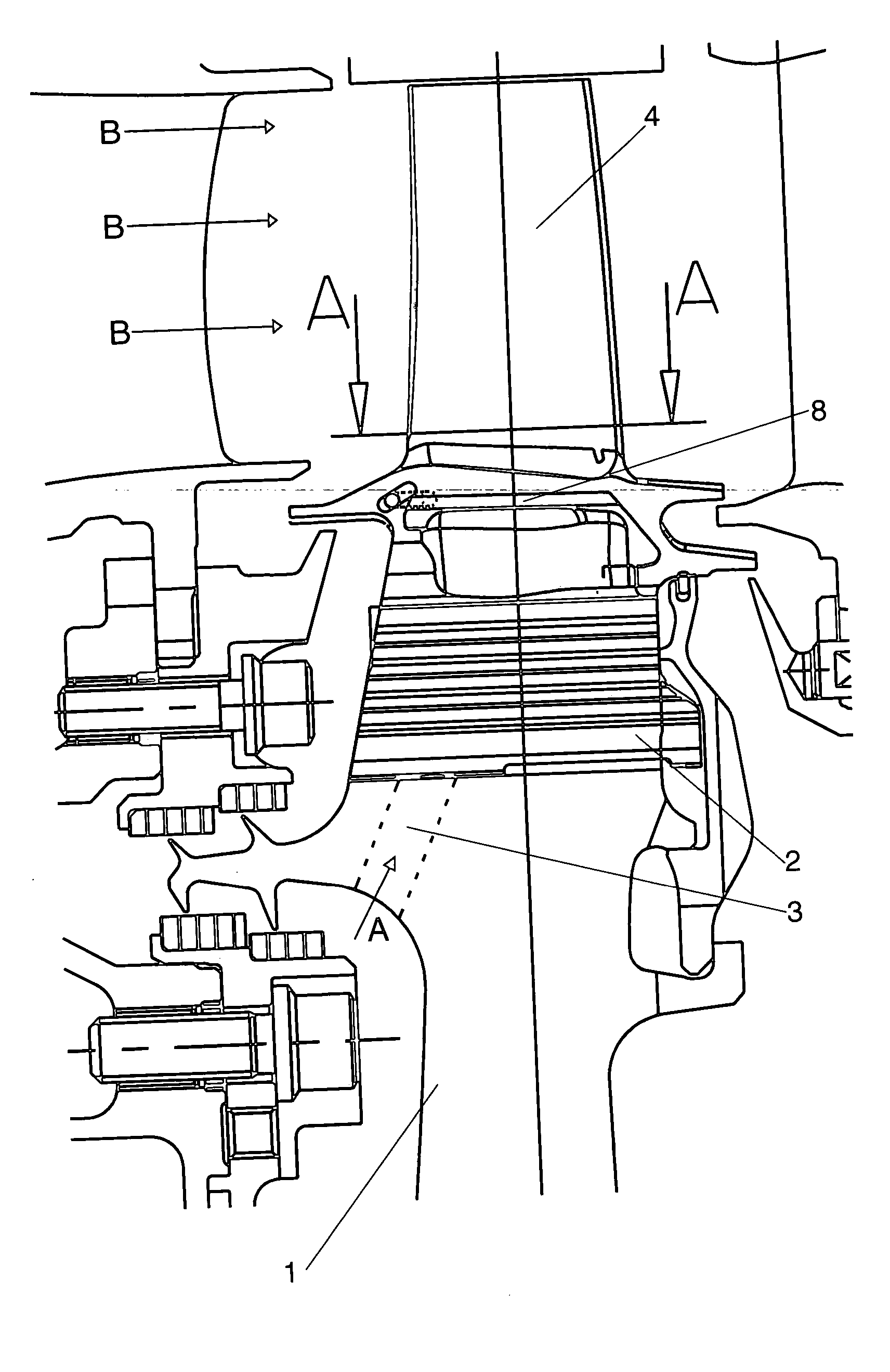
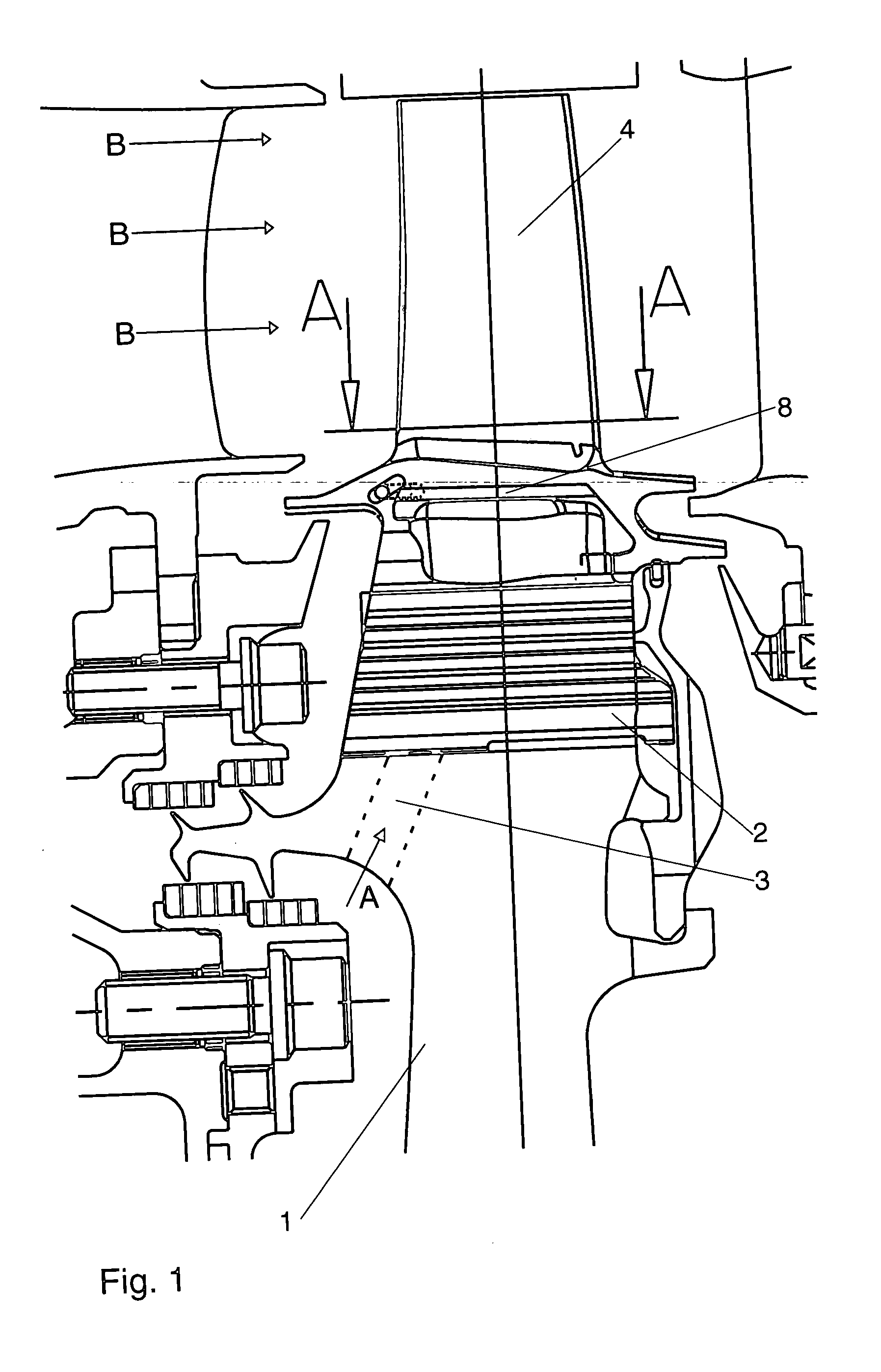
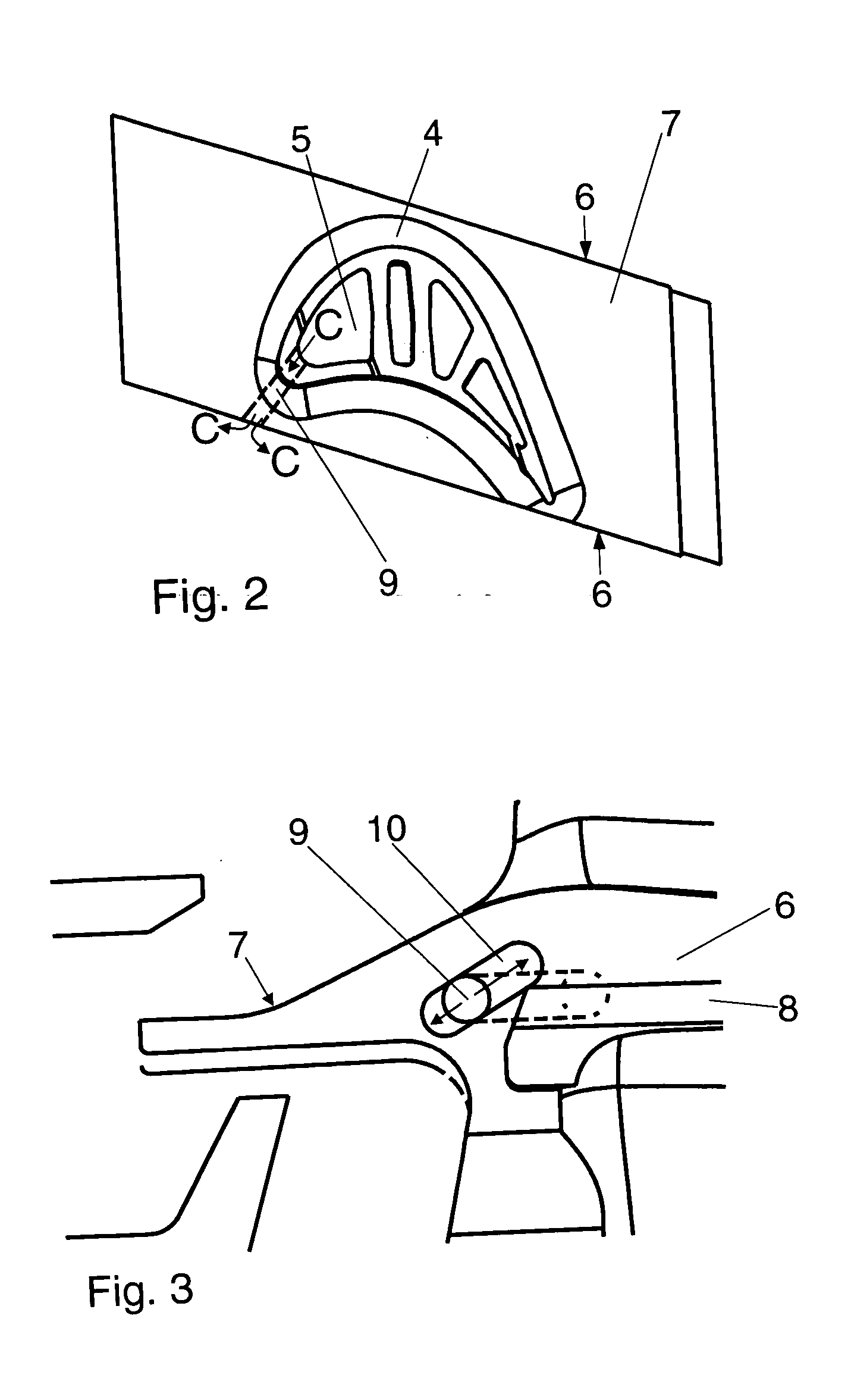
[0015] A multitude of turbine rotor blades is separably fitted—via their blade roots 2—in transverse slots (not shown) on the periphery of the rotor disk 1. Cooling air tapped from the compressor (arrowhead A) enters the cavities 5 in the respective airfoil 4 via cooling air holes 3 in the rotor disk 1 connecting to holes (not shown) in the blade root 2. Thus, the airfoil 4, which is subject to the hot gas flow (arrowhead B), is cooled internally and by means of a film cooling. In a mid-area of the side faces 6 of the platforms 7 of the turbine rotor blades, recesses 8 for the accommodation of a sealing and damping element (not shown) are provided. The sealing and damping elements arranged between the opposite side faces 6 of adjacent blade platforms 7 are intended to limit rotor blade vibration and contact of the turbine disk with the hot gas. Subject to the design of the blade platforms 7 and for manufacturing reasons, the arrangement of the sealing and damping element is confined...


PUM


Abstract

On a gas turbine rotor with internally cooled airfoils (4) of the turbine rotor blades and a mechanical sealing and damping element arranged between opposite side faces (6) of adjacent blade platforms (7), the gap is additionally aerodynamically sealed against the hot gas flow, by cooling air supplied from a cavity (5) of the airfoils via a cooling duct (9) into the gap between the side faces (6).

Description

[0001] This application claims priority to German Patent Application DE102004037331.0 filed Jul. 28, 2004, the entirety of which is incorporated by reference herein. BACKGROUND OF THE INVENTION [0002] This invention relates to a gas turbine rotor comprising a disk and turbine rotor blades held in transverse slots provided at the disk periphery, these rotor blades including an airfoil, a blade platform and a blade root fixed in the respective transverse slot, with the airfoils having cavities flown by cooling air, and with either of the opposite side faces of the blade platforms being provided with a recess accommodating a sealing and damping element bridging the gap between the blade platforms. [0003] Gas turbine rotors of the type described above are known from Specification U.S. Pat. No. 6,561,764 B1, for example. The sealing and damping elements arranged between the side faces of the blade platforms are intended to minimize the ventilation losses and to reduce the vibrations of t...

Claims


Application Information

Patent Timeline
IPC IPC(8): B63H1/20F01D11/00
CPCF01D5/187F01D11/04F01D11/008Y10S416/50
Inventor WHITTON, RICHARD
Owner ROLLS ROYCE DEUT LTD & CO KG
Why Eureka
Try Eureka