Clamp device for long component

a technology of long components and clamp devices, which is applied in the direction of coupling device connections, connection contact member materials, transportation and packaging, etc., can solve the problems of affecting the mounting operation of the clamp device on the stud, affecting the smooth flow of fuel through the line, and affecting the quality of the clamp device. , to achieve the effect of simple clamp device mounting operation

Inactive Publication Date: 2006-02-02
NEWFREY
View PDF8 Cites 6 Cited by
  • Summary
  • Abstract
  • Description
  • Claims
  • Application Information

AI Technical Summary

Benefits of technology

[0012] In this clamp device, the stud fastener comprises a tube for receiving the stud and having a head on one end of the tube, Elastic pawls are formed on the inside of the tube to engage threads or circumferential grooves on the side of the stud. The tube is inserted into the fastener connector of the cover, causing the elastic pawls to engage the threads or circumferential grooves on the side of the stud and causing the clamp and the cover to be mounted on the stud. The tube causes the conductive plates to apply pressure to the side of the stud. Because the clamp and the cover are connected to the stud using a stud fastener, the clamp device mounting operation on the stud is simple.

Problems solved by technology

The friction caused by the passage of fuel or brake fluid through these lines causes them to pick up an electrical charge.
The fuel reacts to the charged line, causing the flow of fuel through the line to go less smoothly.
Sparks also occur on the outer surface of the lines, causing pin holes to develop in the coating on the surface of the lines.
Because the line mounting unit in Patent Document 1 consists of a conductive material such as carbon black mixed into a flexible material such as polypropylene to make the line holder conductive, the unit does not have enough line holding strength.
Also, because a bracket has to be screwed into a car body, the mounting process is complicated and time-consuming.
However, because the electrical connection component is formed separately from the line holding device, the attachment to the line holding device leaves room for improvement.

Method used


Image

  • Clamp device for long component
  • Clamp device for long component
  • Clamp device for long component

Examples


Embodiment Construction

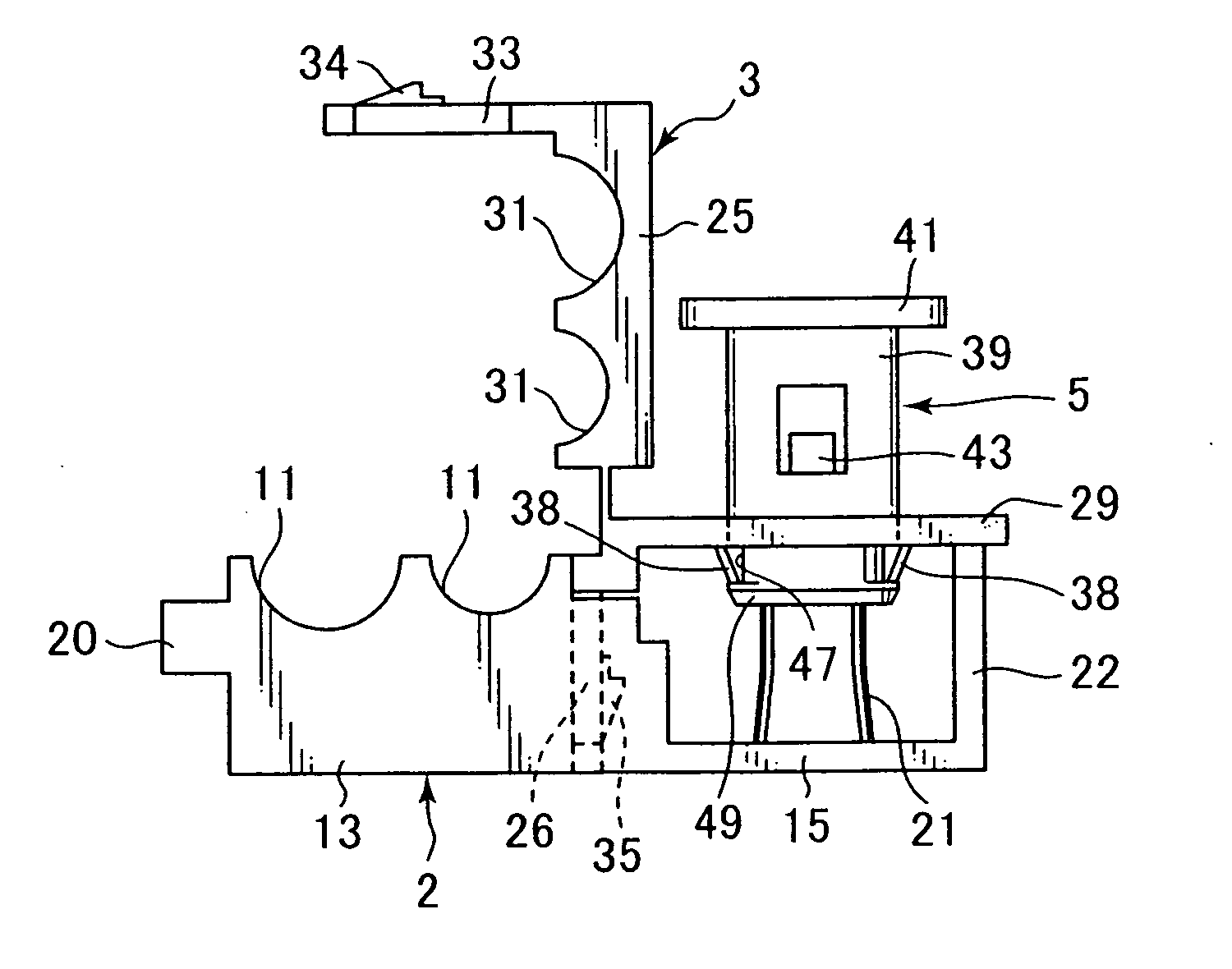
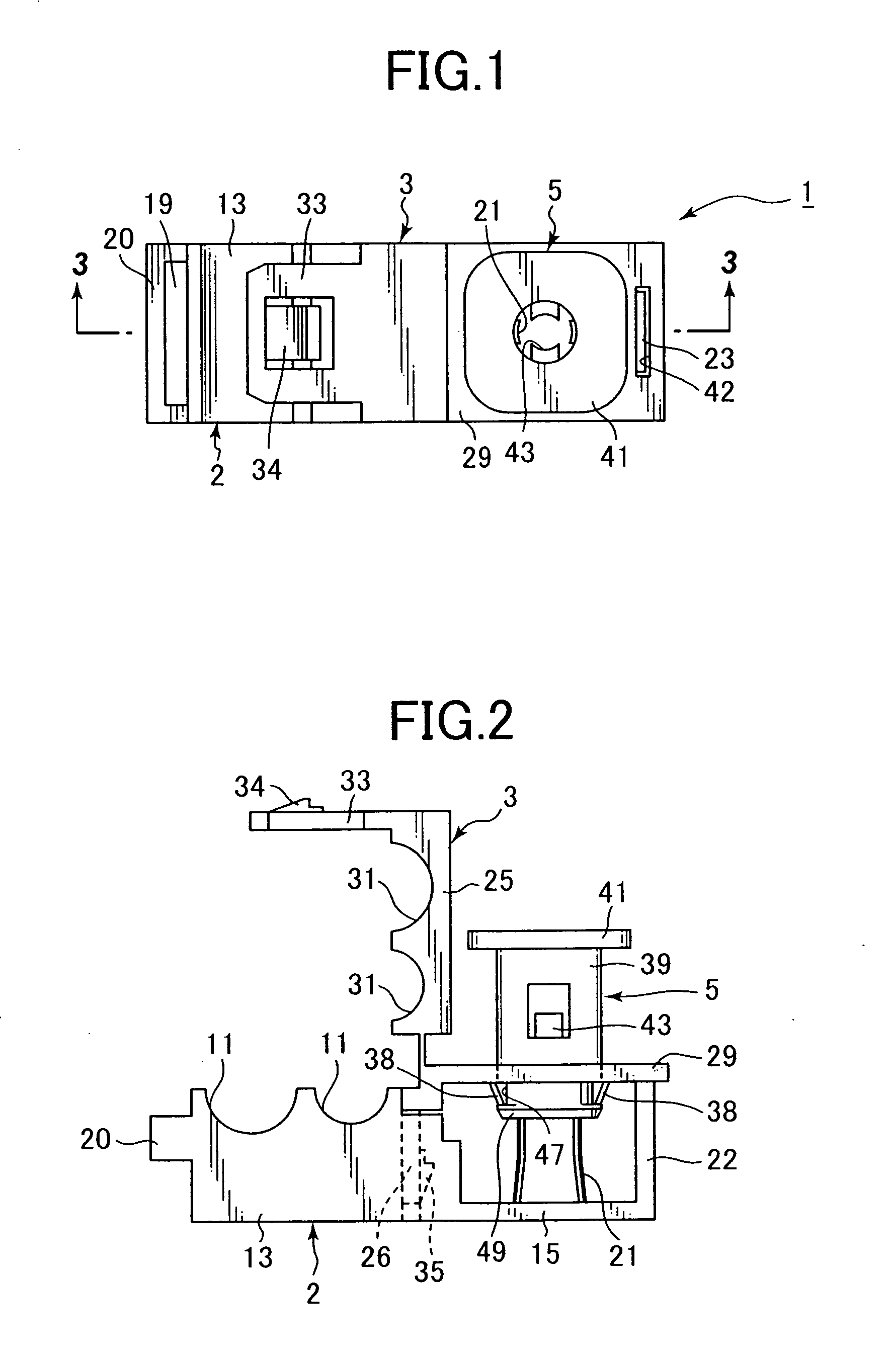
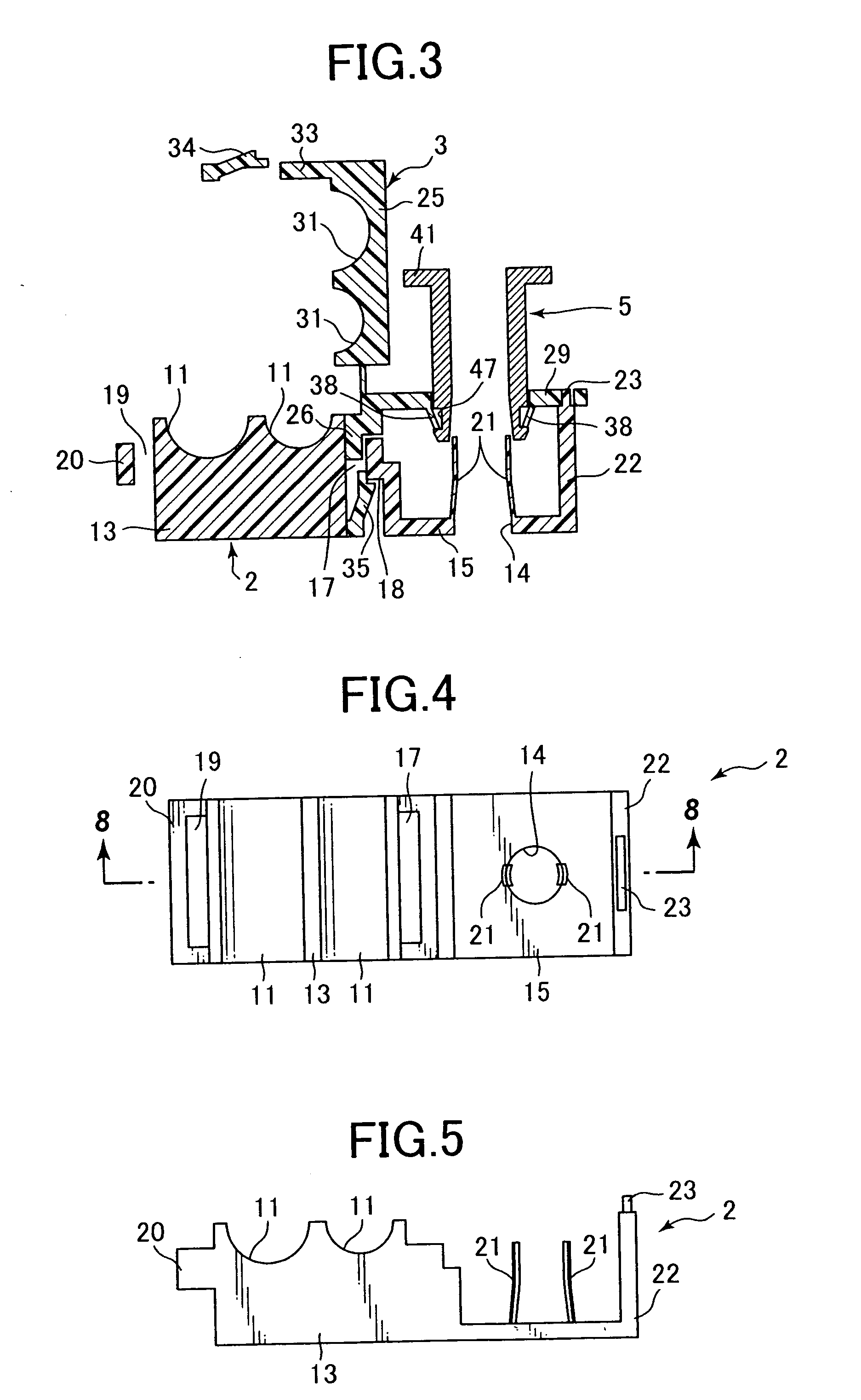
[0038] The following is an explanation of an example of the present invention with reference to the drawings. As shown in FIG. 1 through FIG. 3, the clamp device 1 comprises a one-piece clamp 2 made of a conductive hard plastic for holding one or more long components such as fuel lines, a one-piece cover 3 made of a hard plastic connected to the clamp 2 so as to enclose long components in the clamp 2, and a one-piece stud fastener 5 made of a hard plastic for mounting the clamp 2 and the cover 3 on a conductive stud such as a rod-shaped metal stud bolt attached to a conductive support such as a car body. The cover 3 and the stud fastener 5 have electrically insulating properties, and are both flexible as well as durable. They are made of a hard plastic material such as an engineering plastic. When the clamp device 1 is mounted on a conductive stud, the clamp 2 is connected thereto electrically. As a result, a long component such as a line held in the clamp 2 is connected electricall...


PUM


Abstract

A clamp device for a long component is engaged to a conductive stud attached to a conductive support, in order to conductively mount the long component to the support. The clamp device comprises a clamp made of an electrically conductive hard plastic material having a base for holding the long component, a cover made of a hard plastic material connected to the clamp so as to enclose the long component on the base, and a stud fastener made of a hard plastic material for mounting both the clamp and the cover on the stud and electrically connecting the long member held inside the clamp to the stud. Conductive plates on the clamp contact the stud in the stud fastener.

Description

CROSS-REFERENCE TO RELATED APPLICATION [0001] This application claims the benefit of Japanese Application 2004-223364 filed Jul. 30, 2004, incorporated herein by reference. BACKGROUND OF THE INVENTION [0002] Plastic clamp devices for mounting long components such as fuel or brake lines to car bodies are well known. The friction caused by the passage of fuel or brake fluid through these lines causes them to pick up an electrical charge. The fuel reacts to the charged line, causing the flow of fuel through the line to go less smoothly. Sparks also occur on the outer surface of the lines, causing pin holes to develop in the coating on the surface of the lines. [0003] A line mounting unit is disclosed in Japanese Unexamined Patent Application Publication [Kokai] No. 2000-266240 (Patent Document 1) that solves the problem of charged fuel lines by supporting the lines in a conductive line holder made of carbon black dispersed in polypropylene. This line holder is screwed into a car body u...

Claims


Application Information

Patent Timeline
Patent Type & Authority Applications(United States)
IPC IPC(8): H01R13/648B60K15/01F16L3/10F16L3/237H01R4/64
CPCB60K15/01B60K2015/03401H01R4/64F16L3/237F16L3/1025
Inventor KATO, HIROYUKI
Owner NEWFREY
Why Eureka
Try Eureka