System, apparatus, method, and computer program for radio communication

a radio communication and computer program technology, applied in the field of system, apparatus, method, computer program for radio communication, can solve the problems of reducing the usage efficiency of the transmission line, two hidden stations are not able to negotiate with each other, and the ad-hoc radio lan network is known to be subject to the problem of hidden terminals, etc., to achieve the effect of reducing the amount of interference, avoiding unnecessary channel switching, and increasing the number of communication stations

Inactive Publication Date: 2006-02-02
SONY CORP
View PDF8 Cites 101 Cited by
  • Summary
  • Abstract
  • Description
  • Claims
  • Application Information

AI Technical Summary

Benefits of technology

[0082] In accordance with embodiments of the present invention, the amount of interference is reduced by dynamically assigning the data transmission channel independent of the beacon transmission channel, based on the usage status of the channel and the amount of interference from the other channel.
[0083] In accordance with embodiments of the present invention, the problem of collision is overcome by switching a minimum number of stations in response to a dynamic variation in the network resulting from the shifting of networks or the participation of a new station. Unnecessary channel switching is thus avoided.
[0084] In accordance with embodiments of the present invention, the receiving station can keep track of the packe

Problems solved by technology

This requirement reduces the usage efficiency of the transmission line.
The ad-hoc radio LAN network is known to be subject to the problem of hidden terminals.
Two hidden stations are not able to negotiate with each other, and transmission operations thereof can collide with each other.
In radio communication, it is difficult for own apparatus to receive a signal from own apparatus.
A plurality of networks independently operating using the same communication channel are subject to beacon collision or packet collision if communication coverage areas of the networks overlap each other subsequent to the shifting of one network or removal of a blocking object between networks, for example.
It is almost impossible to overcome this problem in the radio network having a single communication channel.
More specifically, part of the network under interference causes the entire network to be channel switched.
After all, it is difficult to switch the frequency channel in the ad-hoc network.
It is difficult to set up an ad-hoc network without arranging a base station.
Even if a piconet at a different frequency channel is present nearby, communications with a rad

Method used


Image

  • System, apparatus, method, and computer program for radio communication
  • System, apparatus, method, and computer program for radio communication
  • System, apparatus, method, and computer program for radio communication

Examples


Embodiment Construction

[0108] The embodiments of the present invention are described below with reference to the drawings.

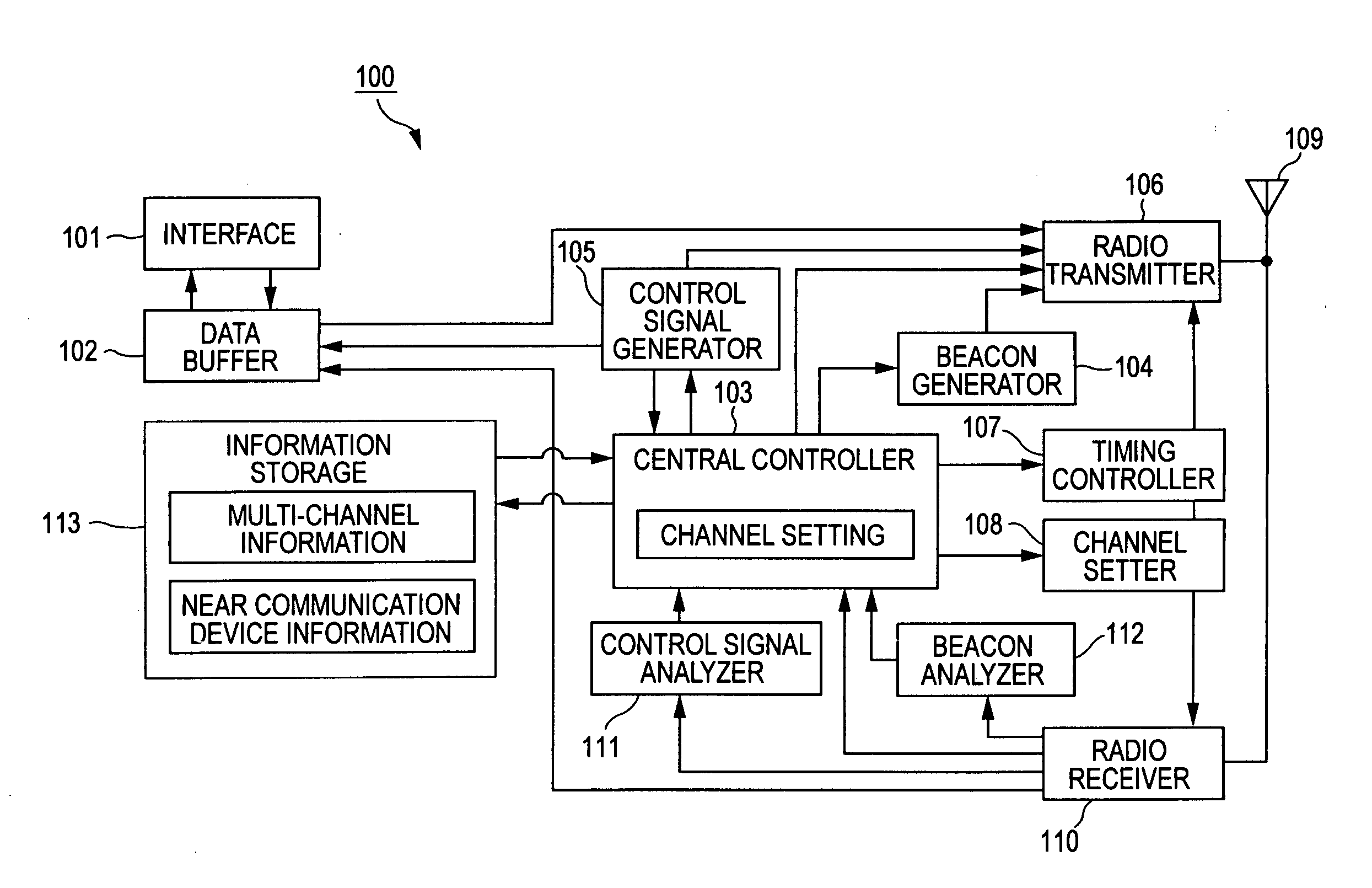
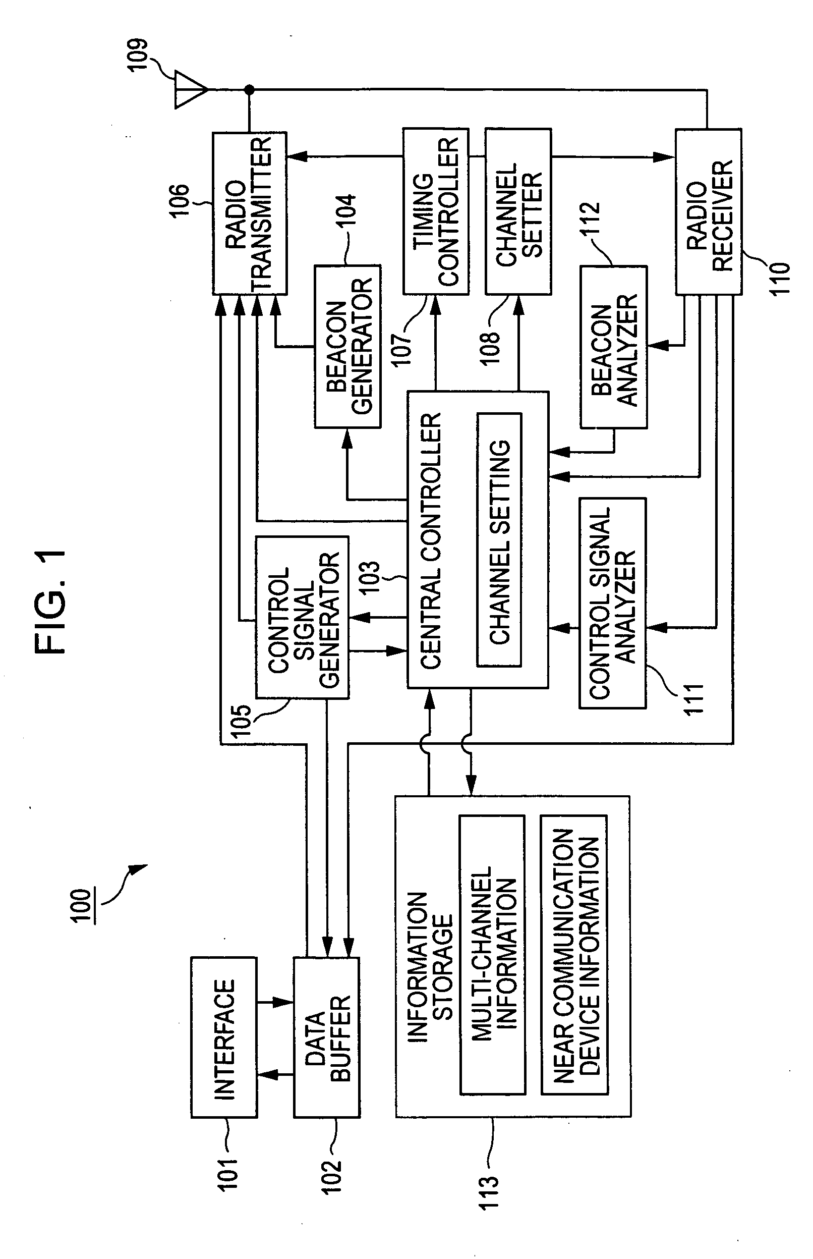
[0109] In accordance with the present invention, radio wave is used as a communication path, and a network is constructed of a plurality of communication stations using a transmission medium of a plurality of communication channels, namely, a multi-channel. Communications are traffic of store-and-forward type. More specifically, information is transmitted in a packet.

[0110] In known multi-channel communication systems, a communication channel is the same frequency channel or a code channel, and a group of communication stations are typically assigned the same communication channel. In contrast, in accordance with a radio communication system of one embodiment of the present invention, the communication station is assigned a communication channel on a per packet basis, and the number of communication stations is thus increased.

[0111] In accordance with embodiments of the present inve...


PUM


Abstract

A radio communication system includes a plurality of radio communication stations. Each radio communication station performs a random-access operation in a communication environment having a plurality of available communication channels, and assigns a communication channel on a per packet basis to transmit a packet.

Description

CROSS REFERENCES TO RELATED APPLICATIONS [0001] The present invention contains subject matter related to Japanese Patent Application JP 2004-220856 filed in the Japanese Patent Office on Jul. 28, 2004 the entire contents of which are incorporated herein by reference. BACKGROUND OF THE INVENTION [0002] 1. Field of the Invention [0003] The present invention relates to a radio communication system, a radio communication apparatus, a radio communication method, and a computer program for performing communications among a plurality of radio stations in a local area network (LAN) or a personal area network (PAN) and, in particularly, to a radio communication system, a radio communication apparatus, a radio communication method, and a computer program for constructing a radio network in which each communication station, free from a slave-master station relationship, performs, in an autonomous distributed manner, a random access operation such as carrier sense multiple access (CSMA) based o...

Claims


Application Information

Patent Timeline
IPC IPC(8): H04Q7/20H04W74/08H04W84/18
CPCH04W52/241H04W84/18H04W74/0816
Inventor FUJITA, CHIHIROSAKODA, KAZUYUKI
Owner SONY CORP
Why Eureka
Try Eureka